How To
If you have multiple workflows to create, that will use the same properties (e.g workflow behaviour, drawing label & reviewers) it’s possible to create a workflow template so the properties do not have to be repetitively assigned.
- Optional: Create a new part for each workflow template you would like to create. The name of the part can be used to give a description of the workflow attributes, to help you keep track of your different templates. These parts can be stored in a folder.

- Create a Workflow as standard and fill out all the desired attributes.
- Favourite the workflow using the star in the header.

- All favourited workflows can be found under the Change items in the TOC. If you un favourite them, they will be removed from this shortcut.

- When creating a workflow to validate your new documents, use the ‘apply workflow template’ button below. This opens a new window where all the favourited workflows are shown, including the various attributes so they can easily be differentiated. Press the button on the left to apply the template, and the attributes will automatically be set.
(Please note: If reviewers are set using the template they are still subject to access rights. These will be checked during the precondition workflow)


More: Design Verification Workflow FAQ
The official CAD tool at CERN for 3D design is CATIA V5. However, the PLM can be used with AutoCAD, BricsCAD, Inventor and REVIT by installing the relevant connector.
Please note there is no support at CERN for the use of these applications, only the installation and usage of the connectors.
Installation steps:
1) Install the 'CERN - PLM Desktop' via CMF.
2) Install the desired CAD package via CMF. If this is not available please contact the service desk with your PC name.
3) Once the CAD package is installed the relevant connector package should be available in CMF. This should be installed. When the CAD package is opened for the first time with the connector you might need to accept the plugin activation.
For more information on the installation steps, and the versions of the CAD software that are supported by the connector, please read the following documentation.
The order of the BOM is determined by the CATIA tree. The BOM is built based on the positions and quantities in the CATIA tree, using a top-down approach.
Please note:
- Only CAD Documents identified as 'Master' 'Representation type' are automatically included in the BOM. See the full FAQ to understand how to manually add documents of alternative 'representation types'.
- The first instance of a reference found in the tree structure is what determines its position in the BOM.
There are manual ways to override the CATIA positions & quantities, for further information on this see the FAQ below. However, you can also simply reorder the CATIA tree to order parts in the BOM as you desire. Use the 'Graph tree Reordering' function in CATIA to easily move the parts around.
The third button in the window can be used to move the part quickly next to any other, by selecting one in the list. Note when moving a part down from its current position, it will be placed under the document you select. When moving up, it will be placed above.

A BOM can be projected onto a drawing using the Title Block Editor (TBE).
When you click on the Title Block Editor icon in CATIA V5,  it will open in a new window. The BOM can be found in the second tab, called “Bill of Materials”.
Check the “Bill of Materials” box to add the BOM to the title block of the drawing. Then click on “Generate & Save” to add the BOM and the title block to the drawing.

More: Title Block Editor FAQ
Further: BOM management in CATIA / PLM
Regular Titleblock stamp:
Case 1: you are working at CERN with an official CAD tool and a PLM Connector (ex: BricsCAD, CATIA etc…).
Thus, you must generate an official CERN Titleblock on your Drawing prior to validating it. Then when a Design Verification Workflow is launched and the Drawing is Approved, this Titleblock will be stamped:
- The banner “Draft for discussion, not valid for execution” will be removed,
- The name of the person(s) who approved the drawing will be added, as well as the date of approval.
- The label defined in the Workflow (ex: For Execution, or For Tender…) will replace the default “Not Valid For Execution”.

Regular CERN Titleblock before validation.

Regular CERN Titleblock after validation.
Mini Stamp:
Case 2: you are not using a PLM Connector, does not matter if you are working at CERN or outside CERN, and you are uploading a native file only.
Examples:
- you are working at CERN with a CAD tool for which there is no connector, therefore no Titleblock Editor, but the format is supported by the PLM,
- you are working at CERN with a CAD tool for which there is a connector, but you chose to not use it,
- you are working in a sub-contractor design office with AutoCAD or BricsCAD, not on the CERN site, thus you do not have access to the CERN connectors, but you have access to the CERN PLM via the web interface,
- you are working at CERN and you receive some drawings as PDF or as DWG from another institute, a contractor etc… that you must upload in the PLM as native file,
For all these cases, it is not possible to have a CERN Titleblock on these drawings, first either because the Titleblock Editor is not available, or because there might be already a Titleblock from another company.
As a result, the regular stamping described in case 1 cannot be done.
Instead, the system will put in place a mini-stamp, which position is customizable, and that will contain the most relevant information (name of the persons who controlled the drawing, date, Label, Reference…).

Mini stamp.
Case 3: you manually upload a viewable file in addition of the native file.
In such a case, does not matter if the native file is connector managed or not, or what the native file type is, the viewable file will always be used for the stamping, with the mini stamp.
Example:
- you are working at CERN with AutoCAD or BricsCAD, and you are working with a multi-sheet drawing.
This feature is not supported by the CERN Multicad connector. But you can save the Native file (*.dwg) via the CERN connector and upload the multi-sheet drawing as a viewable file previously exported as a pdf.
Note: This is not possible for CATIA Drawings.

Native File and Viewable File properties on a CAD Document Profile Card.
- You are working with an authoring tool not supported by the PLM, you upload the native files in a zip file, then, you can upload a pdf as a viewable file.
Said otherwise, as soon as a viewable file is manually uploaded, this viewable file will be used for the stamping, and in that case, a mini stamp will be applied.
In the case that the Drawing was CERN Connector managed, and even if there is a CERN Titleblock generated with the CERN Titleblock editor, this Titleblock will not be used for the stamping, and the mini stamp only will be filled after the validation.
In such a case, it is normal that the banner “Draft for discussion, not valid for execution” remains visible on the bottom right corner.

The position of the mini stamp is defined via the “Design Office” property, that sets a specific position for the mini stamp for each drawing format (A0, A1…).
As a result, this property becomes mandatory and must be filled for any Drawing that is not Connector managed or for which there is a viewable file uploaded.
To see the position that will be applied, from the CAD Document profile go to the Detailed information tab and locate the Design Office property in the Titleblock info & 2D information block.

Click on the link to open the Design Office Profile Card, then check the positions in the relationship grid at the bottom.
The origins are the bottom left corner of the drawing and the bottom left corner of the mini stamp. The units are millimetres.
For instance, in the picture below, we can see that the position of the bottom left corner of the mini stamp for a A4 drawing that is using the EN-EL Design Office property, will be at 30mm of the left edge of the sheet, and at 252mm of the bottom edge.

The first part of the FAQ linked below will show you a quick method of saving a CAD document without dependencies, like a CATPart. The second, more detailed section will describe how to save a structure where the files are linked to each other and will explore the different options available to you from the connector. The final part will explain you how to duplicate a CAD structure.
Please see the video below detailing the first scenario.
More: FAQ
The PLM uses an automatic engineering BOM (EBOM). This means every time you save an assembly the BOM will be created/updated on each 'claimed' or 'new' assembly node.
The BOM uses the positions and quantities of the instances in the CATIA tree, using a top-down approach.
Please note:
- Only CAD Documents identified as 'Master' 'Representation type' are automatically included in the BOM. See the full FAQ to understand how to manually add documents of alternative 'representation types'.
- The first instance of a reference found in the tree structure is what determines its position in the BOM.
- There are manual ways to override the CATIA positions & quantities, see the FAQ below.
You can also trigger a forced manual BOM synchronisation at any time from the “More” menu of the CAD Document profile card in the PLM platform.

The Approved By Integration Workflow can be created from the CAD Document profile card.
There are few basic pre-requirements that the CAD Document must fulfil:
- The CAD Document needs to be in “In Preparation” lifecycle state.
- A Design Code needs to be assigned to the CAD Document through the Part.
In the Profile Card of a given CAD Document, the workflow can be created by selecting the "Create New Workflow" button:

You then need to choose the assignee of the "Design Documentation Check" activity and set the group responsible of the "Review by Approval Group" activity.
Once this is done, the preparation of the Workflow can be finalized by using the "Done" button:

Then launch the Precondition Checks and if you don't meet any issues during this step, you can launch the Workflow. In case there is a precondition check that "FAILED", a specific error message is included for this precondition to help you correct the problem.
As result of the Workflow, the root object and its dependencies will evolve to Approved status.
Complete documentation: Approved By Integration Workflow FAQ
The Approved by Integration Workflow is used to approve Conceptual Drawings and 3D Models, or the envelope of a given equipment.
Its aim is the validation of positions related to functions and beam line equipment, plus reserving space for the development of future equipment.
This Workflow operates on the Integration CAD Structure, meaning the Integration Assembly itself and all its CAD Dependencies, or the Integration (Layout) Drawing.
For this reason, it can only be launched by users holding the “Senior Integrator” role.
The Approved by Integration Workflow is composed of two mandatory control activities that happen “In Series”:
- Design Documentation Check
- Review by Approval Group
Complete documentation: Approved By Integration Workflow FAQ
The CERN PLM can be connected with multiple CAD tools, including REVIT, so that all CERN CAD data is managed in a single enterprise PLM system.
You must first save the project in a local folder. This can be done before launching the save in the PLM, or it will be prompted at the first step. The filename that you set will be used automatically by the connector for the Document Definition. (Once the file has been uploaded in the PLM, the local file created just before must not be edited anymore and can be deleted).

This icon triggers the save of a new project in the PLM. The process will create a link between your project and a Part (existing or to be created).
For more information on the linking of the project to a Part, and information on the connector, please see the following documentation.
The CERN PLM can be connected with multiple CAD tools, including AutoCAD, so that all CERN CAD data is managed in a single enterprise PLM system.
You must first save the file in a local folder before launching the save in the PLM. The filename that you set will be used automatically by the connector for the Document Definition. (Once the file has been uploaded in the PLM, the local file created just before must not be edited anymore and can be deleted).

This icon triggers the save of a new document in the PLM. The process will create a link between your CAD Document and a Part (existing or to be created).
For more information on the linking of a CAD document to a Part, and information on the connector, please see the following documentation.
Ultimate SpinFire is a program that can be used to open CAD Documents saved in a range of file types. It can be used to perform different types of analysis and rendering options, these include;
- Measuring
- Cross-section
- Exploded view
- Rendering Views
For more information on these topics please read the following documentation.
More: How to use SpinFire ultimate as an advanced visualization tool for CAD data?

Manually imported CAD documents cannot be versioned automatically via a connector. Versioning must therefore be done manually in the PLM once the necessary modifications have been made to the CAD document.
The process to follow can be found in the following documentation
Please follow the necessary training before using the PLM. You can access the training and learning path here, this will help you identify what training is necessary for you depending on your previous experience and knowledge.
Training on the CATIA-PLM connector (PWB) is a prerequisite to being granted access to CATIA via the PLM. Once you have completed the training please complete this form to request access to the PLM and CATIA connector.
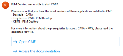
Prior to having the access rights, you will receive an error message when attempting to launch CATIA, and you will not be able to view the connector package in CMF. Please complete the form above.
If you would like a refresher after completing the training please see the document at the bottom of this page, it explains the basic concepts to help you get started. Also see the video below which walks you through the basics steps of using the CATIA connector, such as opening and saving a document.
For more information on some of the steps covered in this video, please see these dedicated how-to's.
- How to access CATIA via the PLM?
- What's the difference between the different CATIA configurations?
- How to search using the PLM dashboard?
- How to open a CAD document from the PLM?
- How to open a CAD document from CATIA using the connector?
- How to save a new CAD document in the PLM from CATIA?
- How to book a specific CERN Drawing Reference before the creation of the Drawing?
- How to set an existing CERN Drawing Reference (CDR) to a new Drawing?
More: FAQ
The Withdrawal Workflow can be created from the Profile Card of Parts, CAD Documents and Documents.

You can then generate the "Precondition Report" that checks the following pre-requirements:
1. You must hold at least one of the following Roles in the Design Code set on the Root Object:
- Contributor
- Equipment owner
- Configuration Manager
- Senior Integrator
Or be member of the Responsible Project Group.
2. That the lifecycle state of the objects affected by the Workflow is not "In Review"
Complete documentation: Withdrawal Workflow FAQ
The Withdrawal workflow is used to withdraw a Part (and all its content), a single CAD Document or a single Document.
According to ISO standards, once withdrawn, an object is no longer available as an active object.
A withdrawn version of an object must no longer be used for any purpose. This means it will not be possible to approve or version any object containing a withdrawn object.
Complete documentation: Withdrawal Workflow FAQ
The Release Workflow can be created from the Part Profile Card.

You can then generate the "Precondition Report" that checks the following pre-requirements:
- Part needs to be in "Approved" or "Replaced" lifecycle state.
- The initiator of the Workflow needs to have the Equipment Owner role in Design Code set on the Part
If all them are fulfilled, you can launch the Workflow that will make the lifecycle state of the Part evolving to Released.
Complete documentation: Release Workflow FAQ
The Release workflow is used to declare that a given Part (and its BOM) is allowed to be used for its intended purpose, meaning that the required item function has been validated.
A Part should be Released when the first asset created from this design is accepted.
Complete documentation: Release Workflow FAQ
To locate, view or open files of SmarTeam(ST) CAD Documents through the PLM platform, follow the subsequent steps.
1. Optional prerequisite to enable the opening of STEP files of ST CAD Document directly into SpinFire Ultimate:
Install the software below from CMF. These are available on any CERN Windows machine.
- CERN - PLM Desktop
- Actify SpinFire Ultimate
Note: There is an embedded viewer in the PLM to allow users to view the documents without installing Actify SpinFire Ult., but for a comprehensive review of a document Actify SpinFire Ult. is required.
For the subsequent steps, use either the PLM Desktop app (open the PLM website as shown below), or open the following link in any web browser, https://plm.cern.ch/. However please note, to open a file directly into SpinFire Ult., the PLM desktop must be running. An explicit error will be returned if it is not.

2. Search for the document in the PLM
2.1 It’s recommended to search for a document through the Folders (ST Projects) and Parts (ST Items) it is in, rather than directly, as these queries load much faster and have improved accuracy. Access these search boxes through the table of contents on the PLM Website (or webpage), as shown below.
Note: the Part (Item) reference can easily be deducted from the ST CAD Doc reference: just remove the _ and the 2 last digits
ex: CAD Doc ref :ST1234567_01 -> Part ref: ST1234567

2.2 Query for the desired Folder or Part using the filter fields. Double-click to open the object in its own window.

2.3 Navigate to the document from the Folder or Part window.
The contents of both objects are shown as icons under the main information boxes, click to open them in their own window. Alternatively, navigate using the ARAS grid and different tabs at the bottom of the window as shown in the images below.


2.4 Ensure you open the required revision of the document. A warning will be displayed in the header of the profile card if it is non-latest, with a link to the latest revision.

3. The 3D data of a CAD Document can be viewed from its Profile Card.
- For quick visualisation there is an embedded viewer window on the right-hand side of the window (installation of Actify SpinFire ult. is not required to view this).
- For a more in-depth review, the data can be opened in the local default CAD viewer using the button below (SpinFire Ult. if installed and the PLM desktop is running).
- To download a .stp file of the document, press the arrow in the top box and choose the filetype from the dropdown list.

4. For a drawing, the 2D data can also be viewed on the Profile Card.
- For quick visualisation there is an embedded viewer window on the right-hand side of the window.
- To download a .pdf file of the CAD Document, press the arrow in the top box and choose the filetype from the dropdown list.
- If it is saved in EDMS, there is also a link to this area.

For more information on how to use SpinFire Ultimate please read the following documentation.
FAQ: SpinFire Ultimate
In order to be able to delete an object from the PLM platform (whether it is a Part, a CAD document, a non-CAD document or a Folder), there are a number of requirements that must be met.
All these requirements and the necessary steps are explained in the FAQ below:
The Fast-Track Promotion Workflow can be created from the Part Profile Card.

You can then generate the "Precondition Report" that checks the following pre-requirements:
- Part needs to be in "In Preparation" lifecycle state.
- The initiator of the Workflow needs to have on of the following roles in Design Code set on the Part:
- Equipment Owner
- Senior Integrator
- Configuration Manager
If all them are fulfilled, you can launch the Workflow.
Complete documentation: Fast-Track Promotion Workflow FAQ
The Fast-Track Promotion can be used to approve the Part without going through a Design Verification, in case the Master CAD Documents are in Approved/Released state.
Once the Part is Approved/Released, you may have the need to just attach to the Part additional documentation, without modifying the Master CAD Documents. In such a case, you need to:
- Version the Part.
- Attach the additional documentation needed.
- Promote the Part by using the Fast-Track Promotion, without going through a formal signature process.
Complete documentation: Fast-Track Promotion Workflow FAQ
It is not possible to validate a single CAD Document in the PLM platform.
The Design Verification Workflow acts on the Part and collects all the CAD Documents and Documents attached to the Part, plus its BOM.
Complete documentation: Design Verification Workflow FAQ
The "Replace By" command can be accessed directly from the profile cards of the following object types:
- Parts
- CAD Documents
- Documents
The command is accessible from the "More" menu  .
.
Please note that the name of this command adapts according to the object from which this command is accessed from. Below shows the "Replace CAD" functionality, available from the CAD Document profile card:

This action opens a popup window from which you will be able to search for the object that replaces the "original" one:

As a result:
- The lifecycle state of the "original" object transitions to "Replaced".
- The Profile Card of the "original" object displays information about the object that replaces it, including a direct link to this replacement Profile Card.

For more information, and explanation of the propagation of this tool, please see the following documentation.
There are few basic pre-requirements that must be fulfilled for being able to perform an Assign Drawing(s) Label Workflow.
CAD Documents set as Root Objects must:
- Be of type "Drawing".
- Be in "Approved" or "Released" lifecycle state.
- Have a Design Code assigned through the parent Part.
Additionally, the initiator of the workflow must hold the "Equipment Owner" role in all the Design Codes set on the Root Objects.
Complete documentation: Assign Drawing(s) Label Workflow FAQ
The Assign Drawing(s) Label Workflow can be created from CAD Documents of type Drawing:

Once the Change Item profile card appears, fill in its Description and choose the Drawing Label you need to apply:

You can change the Label of multiple Drawings with the same Change Item.
To do that, you simply need to add the Drawings by accessing the "Root Objects" tab from Workflow profile card, and selecting the highlighted icon:

You can then launch the Workflow by using the following icon from its Profile Card header:

Please note some of the precondition checks below:
- Check that the user launching the workflow is an 'Equipment Owner' in the Design Code set on the Root Object(s).
- Check that all drawings are in Approved state.
Complete documentation: Assign Drawing(s) Label Workflow FAQ
The Assign Drawing(s) Label workflow is used to change the Label of one or multiple Drawings. This workflow only operates on CAD Documents of type “Drawing”.
As soon as the workflow is launched, this triggers the archiving of the Drawing, taking into account the up-to-date Label, and the generation of the viewable file.
Complete documentation: Assign Drawing(s) Label Workflow FAQ
The Preconditions Report can be run by using the  button from the Workflow Profile Card.
All preconditions have to be “PASSED” for being able to launch the Workflow.
In case a precondition check is “FAILED”, you will receive a specific error message for this precondition so that you can easily fix the problem.

Complete documentation: Design Verification Workflow FAQ
The Design Verification workflow activates the “Control Activities” on the basis of the Control Rule defined on the Design Code set on the Root Objects and on the Parts composing their BOM (as well as on the attached Documents).
The allowed Control Rules are:

Complete documentation: Design Verification Workflow FAQ
Users holding the Contributor role on the Design Code set on the Root Objects of the Workflow can discard / abandon it when the workflow is still in "Active" state.
This implies that there is at least one control activity that must still be completed.
You can abandon the workflow by using the  button → Discard Change Item

Complete documentation: Design Verification Workflow FAQ
You can delegate the Design Verification Workflow activity you have been assign to, to another user holding the role required for its completion (Design Reviewer or Equipment Owner).
To do that, you need to access the "Workflow Activity Completion form" --> Select the "VOTE" button --> Delegate --> choose the new assignee
Then select the "COMPLETE" button to confirm.


Complete documentation: Design Verification Workflow FAQ
Once you access the Profile Card of the Workflow, either using the hyperlink from the notification e-mail, or with My InBasket or via the notification icon on the Dasboard, click on the "VOTE NOW" button (1) available in the "Signs Off" tab, then on "VOTE", and select "Approve" or "Reject" (2).
If you decide to reject, it is mandatory to add a comment.
Then confirm with the "COMPLETE" button (3).


Complete documentation: Design Verification Workflow FAQ
As soon as the workflow is launched, the workflow assignees receive a notification email that contains:
• The reference of the workflow
• The name of the workflow activity the user is asked to vote on
• The direct link to the workflow Profile Card
• The link to the PLM “My InBasket” feature to access the list of all workflow tasks you are responsible for

The My InBasket feature is used to access the list of workflow tasks you are responsible for.
You can access this functionality from the Table of Content → Workflows → My InBasket

You can then access a each workflow Profile Card by clicking on the related hyperlink, in the "Work Item" column

Complete documentation: Design Verification Workflow FAQ
The Valid For Integration Workflow is used to freeze an Integration Assembly at a given point in time. This Workflow operates on the Integration CAD Structure only, meaning the Integration Assembly itself and all its CAD Dependencies.
For more information, please follow the document below:
The Valid For Integration Workflow can be created from CAD Documents.
There are few basic pre-requirements that the CAD Document must fulfil:
- The CAD Document needs to be in “In Preparation” lifecycle state.
- A Design Code needs to be assigned to the CAD Document through the Part.

One the Change Item window appears, then the preparation of the Workflow can be finalized by using "Done" button.

After launch the Precondition Checks and if you don't meet any issues during this step, you can launch the Workflow. In case there is a precondition check that "FAILED", a specific error message is included for this precondition to help you correct the problem.
After approving the Workflow, the impacted objects will be Baselined.
To know more details about this specific Workflow, please follow the document below:
You can define the additional reviewers in the "Additional Reviewers" tab of the Part:

Once the Part is collected by a Design Verification workflow, this will automatically assign them a control activity that must be validated to complete the workflow successfully.
Be careful!! In case you add a group as additional reviewer, an additional control activity will be assigned to each member of this group and the workflow will only be completed once every single user will have validated the control activity they have been assigned to.
Complete documentation: Design Verification Workflow
In case the Control Rule defined on the Design Code set on the Root Object is “QAC A”, the “Review by Approval Group” workflow activity is mandatory, and the system automatically suggests you the Approval Group to use. However, you can decide to assign this workflow activity to another Approval Group defined in the PLM.
For selecting/changing the Approval Group, you need to access the “Approval Group” tab from the Design Verification workflow profile card and select the following icon:  that appears after you have clicked in the field:

Complete documentation: Design Verification Workflow FAQ
The Release For Integration Workflow can be created from a CAD Document.
There are few basics pre-requirements that the CAD Document must fulfill:
- The target CAD Document needs to be in “In Preparation” lifecycle state.
- A Design Code needs to be assigned to the CAD Document through the Part.
In the Profile Card of a given CAD Document, the workflow can be created by selecting the "Create New Workflow" button.

Then the preparation of the Workflow can be finalized by using the "Done" button.

Then launch the Precondition Checks and if you don't meet any issues during this step, you can launch the Workflow. In case there is a precondition check that "FAILED", a specific error message is included for this precondition to help you correct the problem.
The root object of the Workflow will be set to to the Approved status and the impacted objects will be frozen.
For more information, please follow the document below:
The workflow initiator has to select the people in charge of the “Design Documentation Check” and “Part Design Approval” activities from the “Reviewers” tab, available from the Design Verification workflow profile card.
Design Documentation Check: to be assigned to users holding the “Design Reviewer” role.
Part Design Approval: to be assigned to users holding the “Equipment Owner” role.
For assigning the activity to a Reviewer you need to select the icon that appears after you have clicked in the field:

Complete documentation: Design Verification Workflow FAQ
Root Objects represent the set of data you want to approve.
In case you created the Design Verification workflow from the Part profile card, this Part is automatically added as Root Object of the workflow.
It is possible to add multiple Root Objects to the workflow, so that you can approve different Parts with the same Change Item.
To do that, you simply need to access the "Root Objects" tab from the Design Verification workflow profile card, and select the following icon:


Complete documentation: Design Verification Workflow FAQ
The CDD Control 2 corresponds to the Part Design Approval activity in the new PLM platform.
The assignee of this control activity receives a notification email containing the direct link to the workflow object.

Steps:
- Select the link contained in the email to access the workflow object
- Check the objects affected by the workflow in the Impact Tree
- Click on the Vote Now button to sign off the Control activity through the Activity Completion Form

Complete documentation: Design Verification Workflow FAQ
The CDD Control 1 corresponds to the Design Documentation Check activity in the new PLM platform.
The assignee of this control activity receives a notification email containing the direct link to the workflow object.

Steps:
- Select the link contained in the email to access the workflow object
- Check the objects affected by the workflow in the Impact Tree
- Click on the Vote Now button to sign off the Control activity through the Activity Completion Form

Complete documentation: Design Verification Workflow FAQ
The Release by Integration Workflow is used to validate an Integration Assembly.
This workflow operated on the Integration CAD Structure only, meaning the Integration Assembly itself and all its CAD Dependencies if it has a valid lifecycle state (Approved, Released or Replaced). Once we identify the data we need to validate, we must prepare the workflow object (Change Item) and if all the pre-condition checks are passed, then launch the workflow. This sets the “Approved” lifecycle state on the Integration Assembly and automatically completes without any additional control activity.
For more information, please follow the link below:
If the Batch Import has not yet been launched and the job is still "In Preparation", it can be edited (by clicking on the "Edit" button at the top of the Profile Card). Go to the relationship grid at the bottom of the Profile Card, select the row that corresponds to the document (1) to be deleted and choose the "Delete link Document Batch Import" on the right side (2).

For more information, please check the document below:
If the Batch Import has not yet been launched and the job is still "In Preparation", it can be edited (by clicking on the "Edit" button at the top of the Profile Card). Then the new files can be dragged and dropped into the dedicated area. When the import is ready to launch, close the "Edit" mode and click on the "Launch Import" button.
To find more information, please follow the link below:
Every time a file or a batch of files is dragged and dropped into a Part or a Folder in edit mode, the system automatically created an import job. Each job corresponds to a specific object, i.e. a Batch Import, that is created for that purpose in the PLM Platform. That object has its own Profile Card, properties and lifecycle.

To find the specific Batch Import it is possible by going in the Content and then finding "Design and Documents" and next "Batch Import", then retrieve it by the name, the creation date or the Parent.
When dropping a file into one of the two areas, a table appears.


When importing CAD files, the table contains more fields to be completed. As many fields of the table as possible are prefilled but the proposed default values can be changed and the blank fields filled in.
If you require a new document to be created, leave the 'version a CAD document' column blank. To create a new version of an existing CAD document see the dedicated How-to here.
To enter a value or to change an existing value, double-click in the cell in question. To delete a value select the cell and press the "delete" key on the keyboard or copy a value from one cell to another when you have more files by holding the cell on the corner and moving it to the cell below. The metadata can also be copied and pasted from an excel sheet.
Once the metadata has been entered and the upload is complete, the import can be launched by clicking on the blue "Launch import" button.
