How To
The Batch Import can be performed from a Folder or a Part. In both cases, the object must be in edit mode. Once the Folder or the Part is in edit mode, two areas will appear in its Profile Card under “Children” tab.

The files can be dragged and dropped in the desired area.
Dropping files into the area on the left will create or version CAD Documents, which will be linked to the Folder or the Part from where the drag-and-drop operation was launched.
Dropping files into the area on the right will create Documents, which will be linked to the Folder or the Part from where the drag-and-drop operation was launched.
Batch importing involves uploading several files at once to the PLM platform from a File Explorer (Windows, Linux or Mac). To do so, the target folder or part in the PLM must be in edit mode, then the files can be dragged and dropped from the File Explorer into the PLM.
For more information, please follow the link below:
The goal of the Drafts Container functionality is to allow users to approve the Part and its Master CAD Documents without being delayed by the finalisation of the other "secondary" objects that are related to the Part but not relevant for the approval of the Part. On top of that, this functionality allows users to attach "secondary" documentation to the Part at any lifecycle state.
The Drafts Container must be manually activated from the Part Profile Card. You just need to select the  icon and choose “Activate Drafts Container”.
Complete description: Drafts Container FAQ.
The Design Collection replaces the EDMS Drawing Folder functionality and serves to support the data exchange process between the Design Office and the Workshop for the production of a given equipment.
Please find more information in this FAQ:
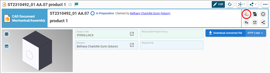
To download CAD files from Parts, Parts attached to Folders, Design Collections or Change Items at once, you need to:
- Access the Profile Card of the object you need to extract the files from
- Select the "Extract files" icon from the Profile Card header

- Choose the BOM Level and what type of CAD files you need
- Select the "Create .zip" button
When executing the "Extract Files" functionality, the selection of the Level applies on the Parts directly linked to the Folder or to the Change Item, or to the Part itself.
The action is now available from the Parts grid in the "More" menu.

This procedure allows the creation and download of a .zip file to your local machine, containing only converted and archived files. CAD native files remain in the PLM.
To print multiple Drawings from your local folder, please read this article.
To print multiple Drawings at once from your local folder in DFS, you need to:
1. Access data in your DFS folder and select all the Drawings you need to print
2. Right-Click and select the option "Open in PDF-XChange Editor"

3. Once PDF-XChange Editor is open, select "File" --> "Print All"

4. Before launching the plotting, make sure that:
- The plotter accepts the format of the Drawings you need to print out
- The highlighted properties are ticked/selected

The Parts are the group of responsible objects for storing all engineering information related to the equipment like 2D, 3D or other documents and files. However, the Part does not contain any files: the files must be attached to the CAD or non-CAD Documents.
In the PLM Platform the Part can be linked to a second Part, but CADs and Documents can be attached only to one Part.
In the Parent Part it is possible to link several Children: Parts (BOM), CAD Documents and Documents.
The Part can be created manually from the PLM Platform or automatically through connector.
Read More: Part
The CGR and Approximate format contains only the graphical representation of the geometry. These options allows you to choose different appearances of the linework of your Drawing.
The CGR files are facetted models for visualisation that can't be edited but they can be used for interference checks. It can also be used as a light representation of a native model that is too heavy for the computer to load, so it is helpful with big assemblies.
The Approximate mode reduces memory consumption and it consumes even less memory and is faster than CGR.
To edit this properties go to the Drawing and right-click on the frame, then select "Properties". Scroll down in the new window and look for the section "Generation Mode". Below you can find the "View generation mode" and from there you can choose CGR or Approximate view.
![]() How to create a dimension relying on a 3D point, projected in a view in approximate mode?
How to create a dimension relying on a 3D point, projected in a view in approximate mode?
To edit this properties go to the Drawing and right-click on the frame, then select "Properties". Scroll down in the new window and look for the section "Generation Mode". Below you can find the "View generation mode" and from there you can choose CGR or Approximate view.
To know more about CGR or Approximate mode, please check the link below.
![]() How to create a dimension relying on a 3D point, projected in a view in approximate mode?
How to create a dimension relying on a 3D point, projected in a view in approximate mode?
To log-out from PLM Desktop you need to click on the button that represents your account (step 1) and use the "Logout" (2).

Then you need to wait for confirmation window that appears and validate.

Even if the Design Code(s) assigned to the Part(s) involved in the Workflow requires 2 Activities (and thus to define 2 reviewers), sometimes only 1 activity is visible in the Reviewers tab of a Design Verification Workflow under edition, and it is not possible to define the second one.

It is possible that by mistake, a filter has been applied on the "Activity assignments".
To remove it, click on this icon  (Clear Search Criteria) and refresh the Workflow
  on top of the page.
All activities will now reappear:

CERN account holders can access the PLM with their nice CERN account.

You need to go to the Design Code Profile Card and click on the tab "Team Members". From there you will find Identities (which are group of users) or users with their "Role".
If you want to see the "Role" in the Team, you can search in PLM Desktop for a Part or CAD Document with its Design Code, open it with this Design Code and click on the button to open the Team with all Identities inside and its roles.
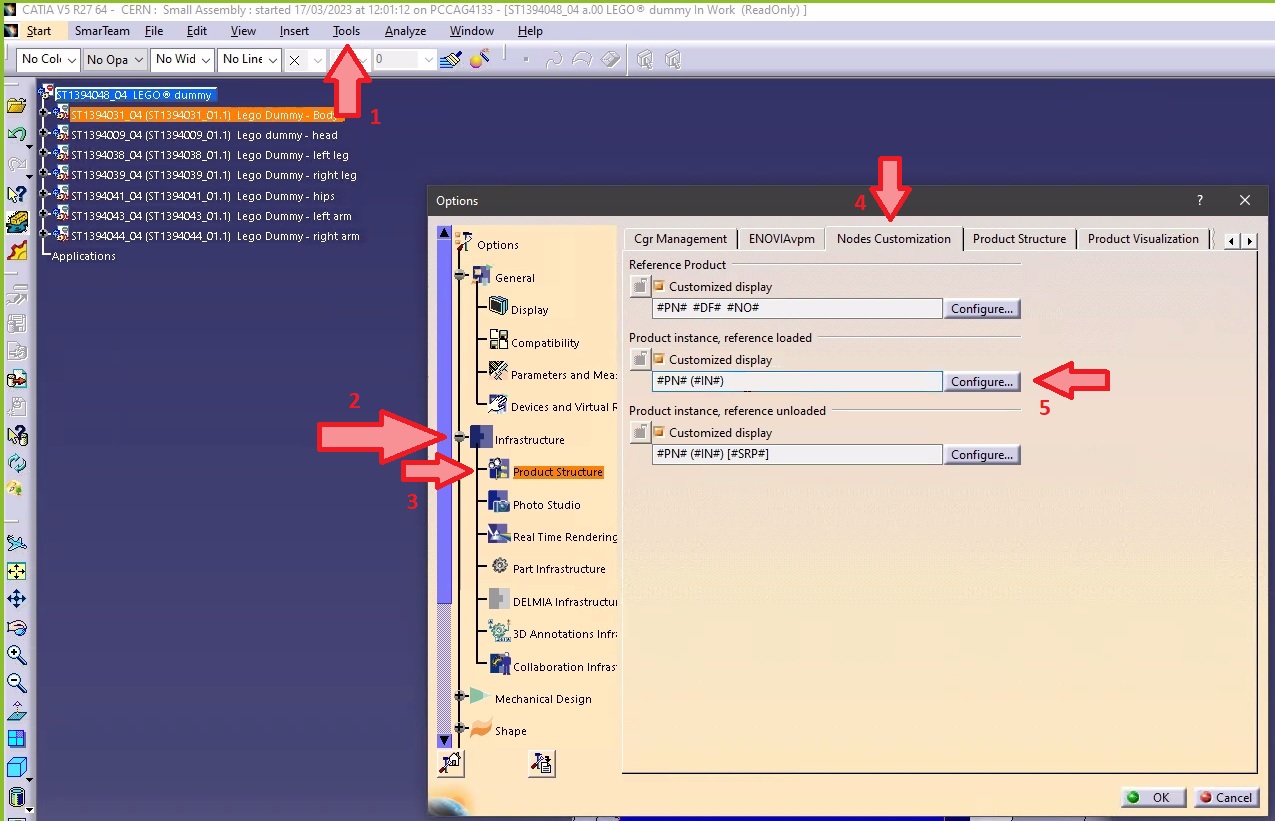
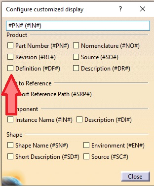
- Go to Tools ➞ Option ➞ Infrastructure ➞ Product Structure ➞ Nodes Customization.
- Tick the "Customized display" (if not already ticked) and open the "Configure customized display" window using the "Configure...".
- In the new window add "Definition" ("#DF") to your product.
- Close. The CAD Definition should be changed in your CATIA tree.
Note 1: if in the same CATIA session, you visualize another product structure from the PLM, the Definition will appear twice.
Note 2: if you want to keep this setting by default for your future CATIA sessions, you need to save your settings.
Once the Workflow object (Change Item) has been launched:
As Creator
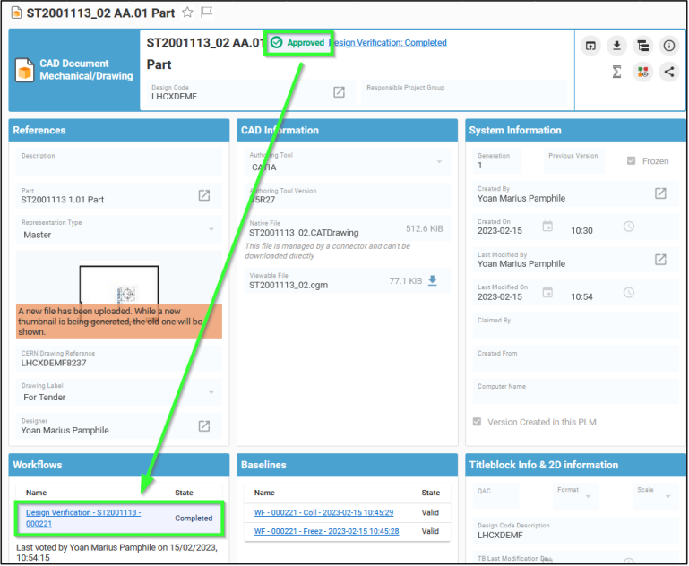
Go to Part/CAD Document from which the Workflow has been launched, then go to the "Workflow" section of the Part/CAD Document Profile Card and click on the link of the corresponding Workflow.
As reviewer
Go to "My Innovator" in the Table of Content, when in "My InBasket". The sought Workflow will be displayed in the table.
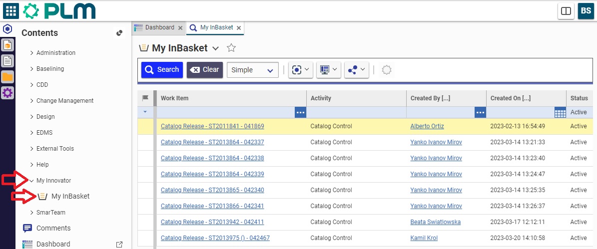
As reviewer, you can access to the profile Card of the Workflow, either using the hyperlink from the notification e-mail, or through the My InBasket page or via the notification icon on the Dashboard.
From the workflow profile card, all the drawing affected by the workflow that need to be reviewed are displayed on the tab 'Affected drawing'.

Click on one of the drawings to open it in its own tab. To view the drawing either open it through the integrated viewer, of download the .pdf.

There are few basic pre-requirements that must be fulfilled for being able to create a Design Verification Workflow:
- The Part must be in "In Preparation" lifecycle state.
- A Design Code must be assigned to the Part.
- The creator of the Workflow must hold the Contributor role in the Design Code set on the Part
You can create and launch a Design Verification by following the information contained in this article.
Complete documentation: Design Verification Workflow FAQ
Once the workflow is launched, the creator of the workflow can, in case of need, reassign the workflow activities (that are not yet completed) to another user. This one must have the role required by the activity (Design Reviewer or Equipment Owner) on all the Design Codes set on the objects collected by the workflow.
For reassigning a given workflow activity you need to access the Reviewers tab of the Change Item ➞ Right-click on the activity ➞ Reassign.

Complete documentation: Design Verification Workflow FAQ
You can create the Design Verification Workflow from the Part by clicking on the icon of the Workflow and then select Design Verification in the drop-down menu. Any already existing Design Verification workflows of the Part that are "In Preparation" will be proposed. Alternatively a new one can be created.

Once the Change Item profile card appears, select the Behaviour of the Workflow, fill in its Description and choose the Drawing Label.

Choose the Reviewer(s) who will perform the control(s), click on Done.
Launch the Precondition tests:

Then launch the Workflow:

The reviewers will receive a notification e-mail to invite them to perform the control.
Complete documentation: Design Verification Workflow FAQ
The Design Verification workflow is used to approve the Design data. Since we are working in Part Centric mode, this workflow allows to approve the Part and all its content. In other words, it will not be possible to approve a single Drawing by using this workflow.
If you want to know more details about designing the Workflow, please follow the document below.
Complete documentation: Design Verification Workflow FAQ
The baseline’s behaviour is determined by the expansion strategy and the filter it uses. The filter corresponds to the type of documents that are assigned (or not) to the baseline.
The only expansion strategy used is the top-down strategy. You can use the filter to assign a baseline to a part, a CAD document or a non-CAD document, provided that the status of the object from which it is generated is “In Preparation”. As stated in the “Baseline propagation” section, the baseline will not propagate to objects that have “Released” status. These objects are already frozen.
After a baseline has been created, the document(s) assigned to it cannot be edited or deleted (lifecycle status cannot be modified). The information about the baseline can be found in the document’s profile card.
The structure covered by the baseline cannot be edited and is frozen. The only way to modify documents is to create a new version of the document in question. Only the version used to generate the baseline is frozen. If a part has several versions, they are not all affected by the baseline.
To more details about this, please follow the document below (page 14).
You are able to create the baseline:
- from the document's profile card - click on the More ➞ Baselines ➞ Create Basic Baseline, the baseline's profile card opens in a new tab.
- from the document search pane, right-click on the line corresponding to the document that you want to include in the baseline, then click on More ➞ Baselines ➞ Create Basic Baselines.
Fill in all the necessary information and generate the baseline, click on the "Generate" button, which is enabled after the baseline has been saved.
To more about baselines, follow the document below.
The purpose of creating a baseline is to freeze any kind of structure (a part or a CAD document) along with all the documents belonging to that structure to which the baseline creator has access.
By creating a baseline, you can:
- save a specific version of a document at a certain moment in time,
- keep a record of how the design evolved,
- prevent a structure from being overwritten by future changes,
- create an official version to share with someone outside the Organization.
The FAQ document below will present the concept, describing its purpose, use, behaviour and consequences.
Most objects can be accessed from a “Properties” window. From there, the “Copy Link” button copies a link to the clipboard that you can then share, giving direct access to that object (in the version you selected) to anyone who receives the link*.
Click on the arrow to choose between the most recent version of the object (“Latest”) or the most recent approved version (“Latest Released”).

* This link is still subject to access rights restrictions; the person who uses the link must have the necessary rights to log into the platform and view the object.
You can navigate the platform using several different interfaces:
- PLM Explorer
- SmarTeam Explorer
- Icons panel
To know more about these interfaces, please follow the document below (page 34).
The “Life Cycle” command displays a map of the life cycle of the object from which the command is launched.
Documents, CAD documents and parts share the same life cycle.
The same map is therefore displayed for all three types of objects.

On the map, the object's current status is shown by a yellow square, not to be confused with the "In Review" status icon.

The “Versions” command grants you access to view all of the versions of a given object.

From the pop up window you can open an old version of the object in a new PLM window. It is also possible to compare two versions using the split screen function, the icon looks like: 
This function is not available for folders, which do not exist in multiple versions.
The "History" command shows you an object's modification history, across all its versions.

The history window displays the dates when actions were taken in relation to the object, as well as other information.
The fields can be customized using the "Refine" and "Display" / "Save Layout" buttons.

The “Where Used” command opens a new window showing where the selected object (in the selected version) is used. Structural links (children → parent links with objects of the same kind) are shown, as are links to objects of different kinds (e.g. a CAD document to a part, a CAD document or part to a folder, etc.). This is bottom-up navigation.
To see the example, follow the document below (page 27).
The “Structure Browser” function allows you to view the structure of the selected object. You can open or close the nodes by clicking on the + or – to the left of each node. With the blue + and – at the top left of the window, you can open or close all the nodes at once.
To read more about this, follow the document below (page 25).
The platform has a table of contents (TOC) on the left hand side. From here you can find all the options to navigate through the PLM to search and create objects.

The platform is navigated using tabs. Every time you open a document, a search or a link, a new tab opens next to the tabs that are already open.
It is largely the same for the four most common types of objects: parts, documents, CAD documents and folders. The menu also exists for other types of objects.
For more information on how to navigate around the PLM interface, and the icons used see the following FAQ.
There are several ways to access the search page, if you want to know more about this procedure, please follow the document below (page 7).
![]() Search Navigation and preferences in the PLM
Search Navigation and preferences in the PLM
See other 'searching' how-tos here
To open the quick search function, first open the Navigation Panel, then select the icon corresponding to the type of object you are looking for or use one of the shortcuts in the sidebar.
The quick search can be used to find an object if you know its reference parameter. This means that the quick search only works if you type in the first character(s) of the reference parameter.

![]() Search Navigation and preferences in the PLM
Search Navigation and preferences in the PLM
See other 'searching' how-tos here
In CATIA, from the connector toolbar, clicking on the Query icon, you will be able to access the PDM Query dialog and to search for any CAD document previously uploaded to the PLM platform. Once the searched CAD Document has been found and selected, a double-click will open it in CATIA.
Note that the double-click corresponds to an Open as Current.

See the 'Opening' subgroup for related information
See more: Open CAD Document in CATIA
Any CATIA document saved in the PLM platform can be opened from there directly in CATIA. There are various methods, see below:
- From Profile card header
- From the PLM dashboard

- From the CAD Document Profile Card.

- From the profile card more menu
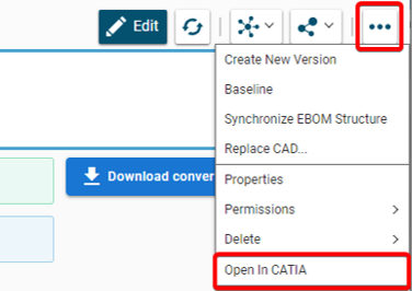
- From a search result grid, using the contextual menu.

See the 'Opening' subgroup for related information
See more: Open CAD Document in CATIA
For support, please send an email to plm-support@cern.ch.
A request will be automatically created in the Service-Now Platform. For urgent/blocking issues, please call the hotline: 160660
For CAD designers, it is also possible to report an issue from the PLM desktop application.

This way, the request created in Service Now will already contain some useful information for the PLM Support Team (PC name, date and time when the applications were launched, CATIA active document reference …).
This is the way to report the problems to be privileged.
Access to the CATIA connector is granted on request, therefore if you have not already done so please complete this form to work with CATIA. Prior to granting you access, we would ask for you to complete the relevant training, please see a link to the learning path to find the best suited course for you.
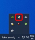
Once your computer is added in the NSC (to complete this process, the admin or the main user of the computer must accept a request sent via email), you will be able to install the CATIA connector via the CERN CMF installation manager, through the icon as shown in the image below.
Note that only Windows 10 physical machines managed by CMF are eligible for CATIA V5 installation.
The main purpose of the toolbox is to design a multi-layer's coil or magnet spacers defined by points coordinates stored in a text file. You can also use this tool to estimate the quality and conformity of generated parts by searching intersection between correspondent coils and spacers. Tool can be used to check the quality of generated spacers by finding distance between the points from text file and the used ones for the design. Tool can be used for exporting constructed data in STEP format.
If you have more questions about this, please check the document under.
To import you need the "Part Template" tool. This can create some 3D points in Catia V5 from their coordinates stored in one Excel file. The created points can be automatically renamed if the name information is available in the Excel file. An optional feature allows building straight lines between every point.
If you want to know details, please check the document below.
The tool that you have to use is a "Power Copy". To use it, a Part must be activated. If you want to know more details, please open the document which is under.
This tool generates a CATPart from a CATProduct, using the "Generate CATPart from Product..." command. Then the tool scans the original Product to search for the materials associated to the parts. It is also possible to run this macro from an existing CATPart generated previously, if the corresponding Product is also opened in Catia V5 to add the material and definition parameters.
If you want to know more about this tool and how to generate this process, please follow the document below.
The "Optimization" workbench is available in Catia V5. It is possible to use it to solve more or less complex problems. You will find in the document below some simple examples in which some optimizations are used and some information on how to put them in place.
The CATIA Knowledgeware regroup a lot of functions: rules, optimizations, templates... that allow you to create generative tools or parametric constructions. Most of the common functionalities we can use in CATIA are contained in "Product Synthesis" solutions.
To start, go to the "Mechanical Design" and then to the "Generative Sheetmetal Design" workbench. Click on the icon and specify the correct parameters of the sheet that you are going to work with: "Thickness", "Default Bend Radius" and "Bend Extremities". The "Sheet Metal Parameters" feature should be added in the specification tree.
If you want to see step by step how to do it, please follow the document below.
The following document has an explanation how to do this step by step. Please check it if you want to know more.
The "Surface Curvature Analysis" is used to find the curvature of the surface or the face of a solid. You can perform analysis in "Part Design" as well as in "Generative Shape Design". If you want to see how the procedure should look like, please open the document below.
Split is an operation where one element is cut by another element.
Trim is an operation in which two elements cut each other mutually.
If you want to see more details and differences between these two functions, please check the document below.
To get the surface from land contour lines you need to proceed from the isolation of the relevant geometry, then the improvement of the quality of the geometry and then the generation and extraction of 3D points. Then you should transform the 3D points into the cloud of points, generate a mesh and then finally auto create a surface feature. If you want to know more details about it, please follow the link below with explanation.