
CATIA - CATPart
Below is a group of How-to's that are related to the topic of 'Solid Modelling' in the CATIA - CATPart subcategory. Click on their links to find more information on these topics.
General:
- How to build parametric models?
- What to do when a CATIA model is having unexpected behaviour?
- How to define a cylinder diameter according to a standard thread?
- How to use Features Recognition Tool?
- How to create a solid from surface?
- How to create a concentric hole in a circular face?
- How to create a 3D text to engrave or create embossed letters?
- How to create a good catalog 3D model?
- What are the Knowledge basics features in CATIA?
Below is a group of How-to's that are related to the topic of 'Sketcher' in the CATIA - CATPart subcategory. Click on their links to find more information on these topics.
General:
- Why use a Positioned Sketch?
- How to use "Constraint Tolerances" in the Sketcher?
- How to create multiple linked corners in the Sketcher?
- How to build parametric models?
- What to do when a CATIA model is having unexpected behaviour?
- How to create a good catalog 3D model?
- How to create a 3D text to engrave or create embossed letters?
Below is a group of How-to's that are related to the topic of 'Open/Save' in the CATIA - CATPart subcategory. Click on their links to find more information on these topics.
General:
- How to create a variant without any impact on the original instance?
- How to open a 3D from the corresponding 2D in CATIA?
PLM Related:
Below are the remaining How-to's that are not present in other subgroups in the CATIA - CATPart subcategory. Click on their links to find more information on these topics.
General:
- How to get the material and the mass in the parts?
- How to use CATDUAV5?
- How to use the CATDUA Automation Tool?
- How to search for elements in a CATIA model?
- How to reposition a solid?
- How to check the quality of a CATIA document using the Q-Checker tool?
- How to use and save Design Tables?
- How to find and change a graphic property?
The Defeaturing tool in CATIA is used to simplify parts by removing recognized features such as holes, fillets, chamfers, and logos. It allows users to define filtering criteria to automatically select which features should be removed.
A recent addition to this functionality is the Logo Filter, which enables the detection and removal of logo features based on parameters such as size, depth, or diameter.
Steps
-
Open a CATPart containing recognized holes, fillets, or logos.

-
Click Defeature a Shape
 in the Part Design Feature Recognition toolbar.
-
The Defeaturing dialog box appears, allowing you to add or manage filters.

-
In the Defeaturing dialog box, click Add Filter
 .
.
-
Select Logo Filter from the list of available filters.
-
Logo Filter (new)
-
Hole Filter
-
Fillet Filter
-
Draft Filter
-
Chamfer Filter
-
You can then define either a minimum or maximum size/depth/diameter to filter out which features/logos would be removed
-
The selected filter is automatically added under Activated Filters.
-
(Optional) Add additional filters (Fillet, Hole, or multiple Logo filters).
-
Click Preview to visualize the features that will be removed.
-
Click OK to apply.

Result
-
Features matching the defined criteria (e.g., logos with a depth up to 3 mm) are removed
-
Multiple filters can be combined, and they are applied using an OR condition (features matching any filter are removed).
-
The Defeaturing feature is created in the specification tree with the applied filters. You can go back into the defeaturing tool from the tree to add/remove/modify any of the filters.
You can quickly remove parts of intersecting closed profiles by using Boolean trimming operations.
Steps
-
Create a sketch
Create a sketch that contains two or more intersecting closed profiles.
-
Select the profiles
Select the profiles you want to trim.
-
Apply a Boolean operation
Right-click any of the selected profiles and choose:
Selected Objects > Add, Subtract, or Intersect
Note: the selected profile must be closed

Commands and Results
-
Add: Combines the selected profiles into one.

-
Subtract: Removes the selected profile(s) from all unselected profile(s).

-
Intersect: Keeps only the overlapping area of the profiles.

Notes
-
Connect curves, conic curves, output features, and construction elements are not affected by Boolean trim commands.
-
For multi-domain profiles, the Boolean operation is applied only to elements inside the profile.
-
Elements that are two layers deep within a multi-domain profile are considered outside of the profile.
With CATIA R35, it is now possible to define the user pattern positions using a single geometrical set (or ordered geometrical set), enabling automatic updates when the set is modified.
The User Pattern command allows you to duplicate a feature, a list of features, or a body at user-defined locations based on 3D points or axis systems. These positioning elements can be grouped within a geometrical set.
Previously, selecting a geometrical set would only use the individual elements inside it. Now, the geometrical set itself can be selected as a whole. As a result, any addition or removal of points or axis systems within the set automatically updates the pattern, without requiring manual re-selection.
Before you begin
Create a geometrical set (or ordered geometrical set) containing the positioning elements for the pattern.
To do this:
-
In the specification tree, right-click the part and select Insert → Geometrical Set (or Ordered Geometrical Set).

-
Create 3D points or axis systems inside the set.
These elements will be used to define the pattern locations.
Steps:
-
Open or create a 3D part containing the feature(s) to duplicate and a geometrical set (or ordered geometrical set) with 3D points or axis systems.
-
Select the feature, list of features, or body you want to pattern. If selecting multiple features, select them in their creation order.
-
Click User Pattern
 to open the User Pattern Definition dialog box. If necessary, adjust the selection in the Object field or choose to pattern the current solid.

-
In the Instances section, click the Positions field and select a geometrical set (or an ordered geometrical set). All points and axis systems contained in this set are automatically used to define the pattern locations.
Note: Only one geometrical set can be used; selecting another one replaces any previously defined elements.
-
In the Anchor field, select a point or an axis system to define how each instance is positioned relative to the original feature.
-
Click Preview to visualize the pattern, then click OK to create it. A User Pattern feature is added to the specification tree.
All instances are created at the locations defined in the geometrical set. Any modification to this set, such as adding or removing points or axis systems, automatically updates the pattern accordingly.

Two new options have been added to the Chamfer command:
-
Hold Curve / Angle
-
Hold Curve / Length
These modes allow you to define the chamfers height based on a selected reference edge or curve (Hold Curve) instead of relying only on standard numeric definitions. This provides better control when the chamfer needs to align with existing geometry.
Points to note
-
The edges to chamfer and the hold curve must belong to the same 3D part
-
Make sure the reference curve is properly positioned relative to the chamfered edge
Steps
-
Open your part.
-
Click on Chamfer.

-
Select the edge(s) you want to chamfer.
-
You can also select a face to chamfer all its edges.
-
In the Mode list, choose one of the new options:
a) Hold Curve / Angle
i) In the Hold Curve field, select a reference edge or curve.
ii) Enter an angle value.


The chamfer is created so that its height is calculated relative to the selected hold curve, while the angle defines the slope.

b) Hold Curve / Length
i) In the Hold Curve field, select a reference edge or curve.

ii) Enter a length value.
The chamfer height is computed based on the distance to the hold curve, defined by the given length.

-
(Optional) Click Preview to visualize the result.
-
Click OK to create the chamfer.

Notes
-
Use Hold Curve / Angle when you need to control the chamfer inclination relative to a reference
-
Use Hold Curve / Length when you need a precise distance from another geometric element
-
These modes are especially useful for designs requiring alignment or parametric control
In CATIA, the Keep Specifications option, previously available for single feature selection, is now also supported for multiple selected features in pattern and mirror commands.
What does it do?
This feature enables you to keep (use) the exact specifications of the original feature(s), on your patterns. To be more explicit, for example for holes drilled with “Up to surface”, “Up to last” or “Up to next” commands, it will keep drilling with this option selected in the patterned holes, otherwise it will pattern simply the first hole length. The difference in these options can be seen at the end of the end of this document.
Steps
-
Create multiple featured parts.


For this specific case 2 holes created, one with “Up to next” and the other with “Up to last” command.
-
Select multiple features in the 3D model (use Ctrl for multi-selection).
-
Launch one of the supported commands:
-
Rectangular Pattern
-
Circular Pattern
-
User Pattern
-
Mirror
-
In the dialog box, enable the Keep Specifications check box.

-
Define the required parameters.
-
Click OK to validate.
Result
The duplicated features keep their original specifications and remain consistent with the source features.

As can be seen, the holes are drilled up to the next/last surface with the option enabled.
When the keep specifications option is disabled, this will result in patterning the first features exactly they are.

The MultiHole command allows you to create multiple holes simultaneously in a part based on a sketch or a set of points, applying the same standard and preset definitions to all of them.
Known Limitations
- Assembly Design Incompatibility: Do not use the MultiHole feature if you plan to use the Reuse Pattern tool in Assembly Design
- Because the MultiHole command does not create a standard “pattern”, the Assembly Design workbench cannot recognize it to automatically instance and position components (such as bolts) across the remaining holes.
- Using MultiHole in this context will force you to manually apply constraints to every single component. If you need assembly automation, use the standard Pattern tool instead.
Using the MultiHole Command
1. Click the MultiHole command.

2. In the MultiHole Definition dialog box, go to the Locations field and define your hole positions using one of the following methods:

i. Click the Sketcher icon to access the sketcher and create the profile you need

ii. Select a pre-existing sketch or points created on your part face

3. Specify your required hole parameters across the tabs (Extension, Type, and Definition).
4. Optional: Click Preview to verify the result before confirming.

5. Click OK.
The MultiHole feature will now be created and grouped in your specification tree.
More: FAQ
The Hole Analysis feature allows you to identify and analyze all the holes present in a 3D part. You can use this tool to filter and review holes based on specific types, diameters, and depth ranges.
Using the Hole Analysis Command
1. With your document open in the Part Design Workbench, select the Hole Analysis command from the Analysis options.

2. In the Hole Analysis dialog box, select the specific hole types you want to review:
- Simple
- Tapered
- Counter Bored
- Counter Sunk
- Counter Drilled

3. To filter the holes by size, check the Main Diameter Range and/or Main Depth Range boxes and specify your minimum and maximum values.
4. Click Analyze. The tool will display the total number of holes found and show the detailed analysis in a table format.

*Note: You can change your filters and click Analyze again at any time to generate a new table.
5. Right-click on any hole in the results grid to access the Center Graph and Reframe options.
6. Click Close when you are finished reviewing the data.
More: FAQ
The enhanced Hole feature in CATIA R35 now allows you to create counterdrilled holes that directly include a countersunk diameter.
Using the Countersunk Diameter Mode
1. Open the Hole Definition dialog box in your part.
2. Navigate to the Type tab.

3. In the Mode drop-down list, select Countersunk Diameter.
4. Specify and modify your required parameters, such as the countersunk diameter, depth, and angle.
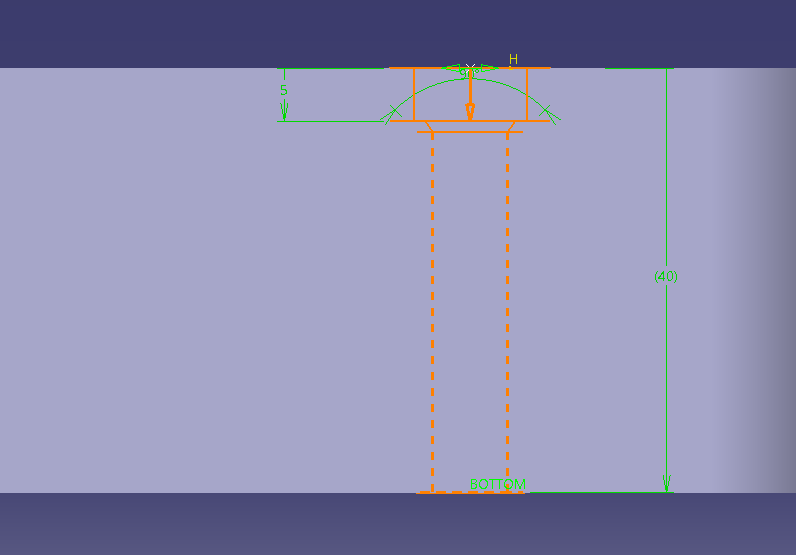
5. Click OK to generate the hole.
More: FAQ
The Pattern Analysis feature allows you to identify and analyze all the patterns present within a CATPart. You can use this tool to filter and review patterns based on specific types and contexts.
Using the Pattern Analysis Command
1. With your 3D Part open, select the Pattern Analysis command from the Analysis options

2. In the Pattern Analysis dialog box, select your desired filters by type and context:
- By Type: Rectangular, Circular, User
- By Context: Solid, Volume, Surface
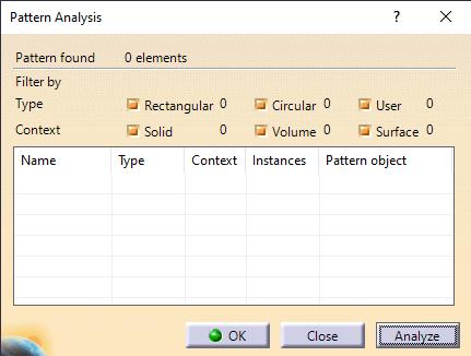
3. Click Analyze. The tool will display the total number of patterns found and show the detailed analysis in a table format.

*Note: You can change your type and context filters and click Analyze again at any time to generate a new analysis.
*Note 2: This is not a shape recognition tool. Holes made from a Boolean operation, pocket, or in a dead solid are not recognized and are not appearing in the analysis table.
4. Click Close when you are finished reviewing the data.
More: FAQ
In the PWB it is possible to open a specific document in context, along with any documents that touch its bounding box in the specified context.
For example, if you have an engine and want to visualise only the parts that surround the crankshaft, this is quickly possible with this function. It prevents the requirement of having to open up the entire assembly, not only saving time but also improving the viewability (only see what is required).
To proceed, first select a CATPart in a PDM Structures window. Then in the contextual menu, click on Show Neighborhood.
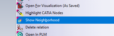
A query window will show up in which you will have to specify the context assembly. The context is the assembly in which the selected CATPart belongs to (the CATPart does not have to be a direct dependency of the assembly, it can be part of a sub-assembly), and in which surrounding geometry will be search for. Double click on the queried context.

The result is a new PDM Structures Window, with the specified context assembly as the root object, that is filtered out with only the CAD Documents whose bounding boxes overlap with the bounding box of the original selected CATPart. You can open this reduced structure in CATIA. The rest of the structure that does not overlap with the main part, will be displayed in the CATIA tree, but no geometry will be loaded*.
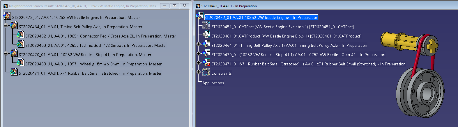
Note: it is only possible to launch the neighbourhood query from a CATPart document, not from a CATProduct. However, it is possible to run several neighbourhood searches in a row. The content of each new PDM Structures Window can be opened and merged in the same CATIA geometry window. Also, the complete assembly can be opened in CATIA at any time.
It is also possible to add a clearance around the bounding box of the selected CATPart, to find more CAD Documents. To modify the clearance value, please go to the connector options and enter the new value.
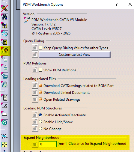
*If these ‘other’ documents have previously been opened in CATIA and their files are in your cache folder their geometry will also be loaded. They will be displayed as new documents, ‘not in PDM’. If the structure is saved these documents will be prompted to be saved as new references in the PLM. It is not recommended to save these. Instead, please close and reopen the structure normally if you need to make changes.
In the PWB it is possible to open on demand only certain selected nodes of the PDM structure in CATIA.
This may be useful when you only need to load a specific set of nodes from a heavy model, but would like to save it in context of the top assembly.
Firstly, open the assembly in the PDM structure window via the query tool, and expand the structure.

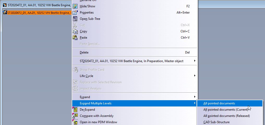
Then, instead of loading the complete structure with “Open” from the top assembly, it is possible to select any number of nodes (CATPart and/or CATProduct) in the tree and run the action “Open in Context” from the contextual menu (right click).
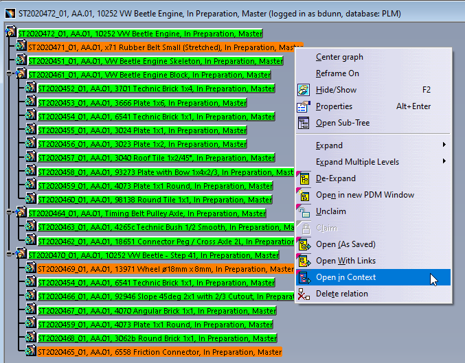
The complete PDM structure gets reduced to only the structure which contains the selected nodes and their parent node. This reduced structure is then opened to CATIA. The documents not selected for partial opening will be shown in the tree but their geometry will not be loaded*.

* However, if these ‘other’ documents have previously been opened in CATIA and their file is in your cache folder their geometry will also be loaded. They will be displayed as new documents, ‘not in PDM’. If the structure is saved these documents will be prompted to be saved as new references in the PLM. It is not recommended to save these. Instead, please close and reopen the structure normally if you need to make changes.
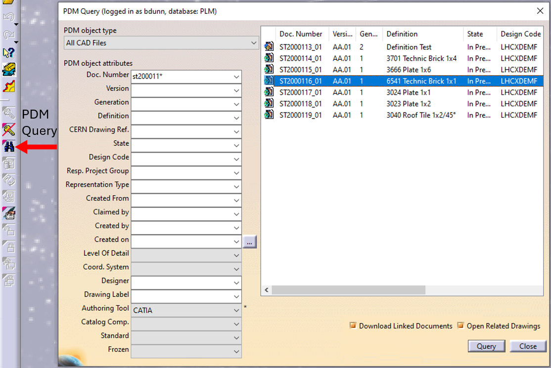
In CATIA, from the connector toolbar, clicking on the Query icon, you will be able to access the PDM Query dialog and to search for any CAD document previously uploaded to the PLM platform. Once the searched CAD Document has been found and selected, a double-click will open it in CATIA.
Note that the double-click corresponds to an Open as Current.
See the 'Opening' subgroup for related information
See more: Open CAD Document in CATIA
Any CATIA document saved in the PLM platform can be opened from there directly in CATIA. There are various methods, see below:
- From Profile card header
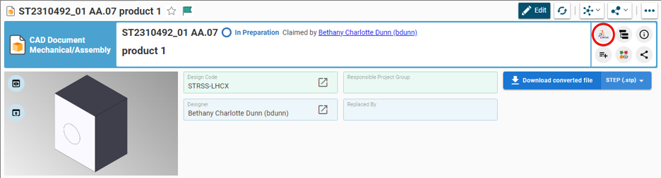
- From the PLM dashboard

- From the CAD Document Profile Card.

- From the profile card more menu
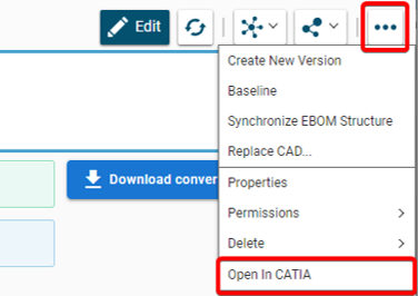
- From a search result grid, using the contextual menu.

See the 'Opening' subgroup for related information
See more: Open CAD Document in CATIA
Often enough, there is a need to switch between a 2D opened in CATIA to its corresponding 3D. In order to facilitate and quicken this task, it is possible to open the 3D directly from the 2D. To know more about this procedure, please check the document below.

In an assembly, it is possible to duplicate a part or a product in order to create a variant without the original instance is impacted or even replaced with the new in the current session. There are few steps how to do it and you can find in the document below.
Now it is possible to add, modify or delete "Constraint Tolerances" in the Sketcher. These are also visible in 3D and in the Drawing.
For more information about this, please follow the document bellow which exactly describes how to do it.
A Design Table is designed to drive the parameters of a CATIA document from external values. These values are stored externally in the form of a table. Design Tables help in the tasks of creating and managing component families. These components can be, for example, parts differing only in their parameter values.
In the document below, you can find a methodology of creating a new Design Table or how to use an existing one.
In the document below, there is a procedure to create text for engrave or embossed. One example of use is when is needed to represent in 3D the stamping of letters and numbers in an object. Please follow this procedure to understand it.
There exist several possibilities to create a solid from one or many surfaces. If you want to understand it more, please click on the link below.
After a transfer (from Euclid, for example) certain solids must be repositioned relatively to the reference planes. The document below presents a procedure that allows you to do this.
With positioned sketches, the origin and directions of the absolute axis are similar to external references (Use-Edges) obtained using additional projections or intersections when creating non-positioned sketches. If the 2D geometry is under constrained and you move or resize the part (no matter how significantly), the profile you sketched will remain absolutely unchanged. It is also easy to copy and reuse in another place (since you don’t need to use external references).
For more details about this operation, please click on the document below and read it.
To create a hole by selection with a circular face (from a prism or from a hole), by default the created hole is centered on this face, but there is no constraint automatically created. As a consequence, if the face (support) moves, the hole is no longer centered. The solution is to edit the hole's sketch and add some constraints.
Another method is to create the hole with a concentric constraint with the face.
To understand more, please check the document below.
It is possible in a single operation to apply the "corner" according to several corners, with the same radius value.
In addition, all values are related, so that the change in one of these changes the values of the others.
Please explore more about corners in the document below.
The graphic properties tool you can find in the top bar of the main CATIA workbenches.
To know more how to change them step by step, follow the document with instructions which is under.
Parametric modeling aims to make “intelligent” models, which are directly driven by specifications, and which integrate the various knowledge around a project.
The link below will present the methodology and the basic tools and rules to follow in order to build parametric models or parts in the CATIA V5 environment.
Q-Checker is a tool that checks the quality of a CATIA document. It will be automatically installed via CMF in all the PCs in the CATIA group.
If the tool is installed, in all the CATIA workbenches will appear this icon which is below.

When it is needed to work on a dead body model, you may be required to remove a certain feature, or simply edit it. To get to this, the feature recognition functions built into CATIA allow adding them their construction history, from which you shall be able to edit or remove them at will.
If you want to know more about this process, please check the document below.
To get the mass in a CATPart it’s important to put the material in the correct place in the document. The correct place to put the material is in the Part (and NOT in the PartBody). It’s important to follow this rule since the material in SmarTeam profile card will be taken from the part properties. If you put the material in the PartBody, SmarTeam will not show any material in the profile card.
In the link below you can find procedures step by step how to do it.
It is possible to clear CATIA models from internal errors by:
- doing it one by one interactively,
- for several CO models simultaneously,
- for all models in a folder at once using a batch tool.
To follow step by step how to do it, please click on the link below.
When Catia V5 files are manipulated, errors can appear, leading to troubles like ghost links. To solve this, the CATDUA (For Catia Data Upward Assistant) exist in the Catia V5 Desk This tool is powerful, but only treat documents one by one which can be painful for users, when dealing with assemblies. So, in order to facilitate the cleaning of models, CATDUAV5 Automation has been developed by support.
To learn more about this process, please refer to the document below.
A catalog 3D model is a 3D model of a commercial component, and/or a normalized element, or a usual element widely used at CERN.
There are four ways to get 3D models.
- From an existing template.
- From a downloaded STEP file.
- From zero.
- From a downloaded macro.
Here is a guideline to help you in the creation process ➞ catia-catalogs@cern.ch.
If you want to know more about this process, click on the link below.
In the document below you will find a detailed explanation of how to search for components in CATIA.
Below in the document there are a few steps to debugging CATIA models.
Be careful, make sure that the "Save" operation worked well before to close SmarTeam and Catia V5.
If "YES" have a look on following advise below: In case of doubt ➞ HotLine 16 06 60