CATIA - General
Below is a group of How-to's that are related to the topic of 'Open/Import' in the CATIA - General subcategory. Click on their links to find more information on these topics.
General:
PLM Related:
- How to open a CAD document from the PLM?
- How to open a CAD document from CATIA using the connector?
- How to preview a CAD document in CATIA from the PLM?
- How to Open a structure in context (partial loading)?
- How to open via neighbourhood search (Spatial search and opening)?
- How to use the Emergency Save (Upload) and Open function of the CERN CATIA PLM toolbox?
Below is a group of How-to's that are related to the topic of 'Print/Export/File Type' in the CATIA - General subcategory. Click on their links to find more information on these topics.
General:
Below is a group of How-to's that are related to the topic of 'Views & Positioning' in the CATIA - General subcategory. Click on their links to find more information on these topics.
General:
- How to save a point of view in one assembly?
- How to move a part while preserving the same coordinates system?
- How to move an assembly to another position while respecting the coordinates?
- How to orientate the 3D view plane respecting the custom H and V directions?
- How to modify display or orientation by default in CATIA?
- How to realize a 3D breakout view?
Below is a group of How-to's that are related to the topic of 'Best Practices' in the CATIA - General subcategory. Click on their links to find more information on these topics.
General:
- How to hide all the planes in an assembly?
- How to build parametric models?
- How to avoid creating large size Assemblies?
- How to avoid contextual links?
- What to do when a CATIA model is having unexpected behaviour?
- What are the parameters which impact the CGR file size?
PLM Related:
Below are the remaining How-to's that are not present in other subgroups in the CATIA - General subcategory. Click on their links to find more information on these topics.
General:
- What are the CATIA Acronyms?
- What are the meanings of the CATIA & PLM Icons?
- Who to contact for support?
- How to get the material and the mass in the parts?
- How to search for elements in a CATIA model?
- How to hide all the planes in an assembly?
- Why the instance names do not have the same number as the instance name?
- How to find and change a graphic property?
- What are the parameters which impact the CGR file size?
- What to do when a CATIA model is having unexpected behaviour?
PLM Related:
- How to access CATIA via the PLM?
- How to save a new CAD document in the PLM from CATIA?
- How to make the definition visible in CATIA tree when working with files not stored in PLM?
- How is metadata managed between the PLM and CATIA?
- How to save customised CATIA & PWB settings?
- How to check if a document is 'current'?
Below is a list of acronyms that are used in relation to CATIA.
- BOM – Bill of Materials
- CGR – CATIA Graphical Representation
- GSD – Generative Shape Design
- PWB – PDM Workbench (PLM-CATIA connector)
- TBE – Titleblock Editor
- WB – Workbench
See the list of PLM Acronyms here.
See the list of SmarTeam Acronyms here.
To access CATIA via the PLM please press the CATIA icon in the top right of the dashboard screen.
Access to the CATIA connector is granted on request, therefore if you have not already done so please complete this form to work with CATIA. Prior to granting you access, we would ask for you to complete the relevant training, please see a link to the learning path to find the best suited course for you. Once you have been granted access you will have to download the required programs from CMF.
If you do not have the connector installed, or it is an out of date version, you will receive the following message when attempting to launch CATIA through the button on the PLM dashboard. This will remind you which applications must be installed and a link to CMF. There is also a link to documentation explaining the prerequisites required before running this application.
If CATIA is not installed the launch button will be greyed out.
To prevent data loss caused by save interruptions (for example, switching windows too quickly after pressing "Save"), a CATIA Connector update was deployed on Wednesday, 5th of November. This update introduces a temporary but safer save mechanism.
Key Changes Implemented
Save Dialog is now mandatory for ALL save operations
- Previously, the Save Dialog appeared only on the first save to PLM Platform.
- The follow-up saves were handled via an asynchronous upload mechanism, which has now been removed.
Synchronous save process enforced
- Users must now wait until the file upload is fully completed before continuing.
- CATIA Connector icons will no longer blink during the save process.
Save must be explicitly confirmed
- After clicking Save (or CTRL + S), users must not switch CATIA windows or use CTRL + TAB.
- Wait until the “Save to PDM?” dialog appears.
- If the dialog does not appear, click Save again and wait.
- The save operation is validated only when the dialog informs the user of "Action succeeded" in the button left corner.
- Do not navigate away to another CATIA window until the process completes.
- You may then safely close the dialog.
Save Dialog Feedback Types
The Save Dialog Summary may show different feedback:
Type 1 – Modifications to an existing PLM document are being saved.
Type 2 – A new document is being saved; the PDM Create window will open after Save.
Type 3 – No save occurs because the document is read-only (unclaimed; “Locked By” is empty).
Type 4 – The operation shows Create, but the document already exists in PLM.
- If the CATIA Part Number starts with “ST” and no duplicate operation was performed, the document is not recognized by the connector and will be saved under a new reference.
If you're experiencing delays or failure when saving through the standard CATIA Connector, you can use the Emergency Save (also called Toolbox) function as a fallback to manually upload your work.
You can also use this tool to open existing CAD Documents for which you already experienced issues when opening or saving.
This guide walks you through the required steps, important limitations, and best practices to ensure your data is securely backed up.
Known Limitations
- No New Documents: The Toolbox will not handle new (never saved) CAD documents. These must be handled with the standard CATIA Connector before using this feature (see below).
- No BOM Computation will be launched after the save via the Toolbox. And running the e-BOM sync from the Profile Card of the assembly will not work.
So, at a point in time, it will be mandatory to save your structure with PWB, or to consider to update your BOM manually. - The CAD Documents open in CATIA using the toolbox will not display any PLM metadata in the CATIA tree, and appears as “Not in PDM”, thus cannot be saved using the usual CATIA Connector save. But they can be saved via the toolbox.
Using the Toolbox Save Command
If after a regular CATIA Connector save, you notice a failure, you can use the Toolbox Save Command.
The connector will save all the CAD Documents which are claimed in PLM AND modified in the CATIA Session before uploading them in the PLM.
- Let your CATIA session running. DON’T log off from the Catia Connector.
- Close the CATIA Connector Save window (if relevant).
- Access the tool, following this path in your file explorer:
\\cern.ch\dfs\Applications\PLMApps\CATIAPLMToolbox
and click on StartCATIAPLMToolbox_v1.exe
Note: for a regular usage, you can copy this shortcut on your desktop:
StartCATIAPLMToolbox.bat - Shortcut.lnk - The tool will start and will be associated to the PLM Desktop:
- Click the Save & Upload button.
- Read carefully the report and check the result in the PLM.
In case of doubt, call the CAD & PLM Support team.
Using the Open Command
- Open the CATIA session (or if CATIA is already running, use this session).
You do not have to log-in to the PWB CATIA Connector. However, if you want to work with PWB with other CAD Documents or if you will have to save brand new CAD Documents to the PLM, you must log-in. - Access the tool following this link:
\\cern.ch\dfs\Applications\PLMApps\CATIAPLMToolbox\StartCATIAPLMToolbox_v1.exe
Note: for a regular usage, you can copy this shortcut on your desktop:
\\cern.ch\dfs\Applications\PLMApps\CATIAPLMToolbox\StartCATIAPLMToolbox.bat - Shortcut.lnk - Click on Open and use the filters in the new pop-up window that appears to find the CAD document to open.
- Select it and in the “Open in CATIA” window, choose the expand strategy and the options you need, then validate.
- The tool will download the necessary files to your local machine then will open the selected CAD Document in CATIA.
Attention, CAD Documents open via the toolbox can only be saved with the toolbox. (And not via the usual CATIA Connector save)
Using the Open Profile Card Command
- Select one or several Documents or instances node in CATIA (the selection of features in a CATPart will be ignored)
- Click on the Open Profile Card button.
The Profile Card(s) corresponding to your selection will be displayed in the PLM Desktop.
Best Practices
- Use the Toolbox only as a last resort when standard saving is not responding, reports an blocking error or is taking too long or if you already experienced an issue when working with the same CAD Document.
- Always verify the saved structure afterward within the CATIA Connector interface.
Check for each of your recent modified and saved CAD Documents that the date & time of last modification of the native file is coherent with the save time.
- Notify the PLM Support Team if you consistently encounter performance issues or errors with the standard CATIA Connector.
- When you are aware that opening a given CAD Document returns an error, open directly via the Toolbox.
- In case you have inserted a new CAD Doc in your CATIA structure you are about to save with the toolbox:
Open this new CAD Doc in the new CATIA Window, save it using the CATIA Connector, and come back to the assembly window to save the assembly with the toolbox.
If you need further assistance, please reach out to our support team via the Contact Page or consult the detailed troubleshooting guide for CATIA connector issues.
In the PWB it is possible to open a specific document in context, along with any documents that touch its bounding box in the specified context.
For example, if you have an engine and want to visualise only the parts that surround the crankshaft, this is quickly possible with this function. It prevents the requirement of having to open up the entire assembly, not only saving time but also improving the viewability (only see what is required).
To proceed, first select a CATPart in a PDM Structures window. Then in the contextual menu, click on Show Neighborhood.

A query window will show up in which you will have to specify the context assembly. The context is the assembly in which the selected CATPart belongs to (the CATPart does not have to be a direct dependency of the assembly, it can be part of a sub-assembly), and in which surrounding geometry will be search for. Double click on the queried context.

The result is a new PDM Structures Window, with the specified context assembly as the root object, that is filtered out with only the CAD Documents whose bounding boxes overlap with the bounding box of the original selected CATPart. You can open this reduced structure in CATIA. The rest of the structure that does not overlap with the main part, will be displayed in the CATIA tree, but no geometry will be loaded*.

Note: it is only possible to launch the neighbourhood query from a CATPart document, not from a CATProduct. However, it is possible to run several neighbourhood searches in a row. The content of each new PDM Structures Window can be opened and merged in the same CATIA geometry window. Also, the complete assembly can be opened in CATIA at any time.
It is also possible to add a clearance around the bounding box of the selected CATPart, to find more CAD Documents. To modify the clearance value, please go to the connector options and enter the new value.
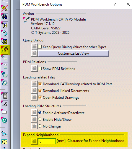
*If these ‘other’ documents have previously been opened in CATIA and their files are in your cache folder their geometry will also be loaded. They will be displayed as new documents, ‘not in PDM’. If the structure is saved these documents will be prompted to be saved as new references in the PLM. It is not recommended to save these. Instead, please close and reopen the structure normally if you need to make changes.
In the PWB it is possible to open on demand only certain selected nodes of the PDM structure in CATIA.
This may be useful when you only need to load a specific set of nodes from a heavy model, but would like to save it in context of the top assembly.
Firstly, open the assembly in the PDM structure window via the query tool, and expand the structure.

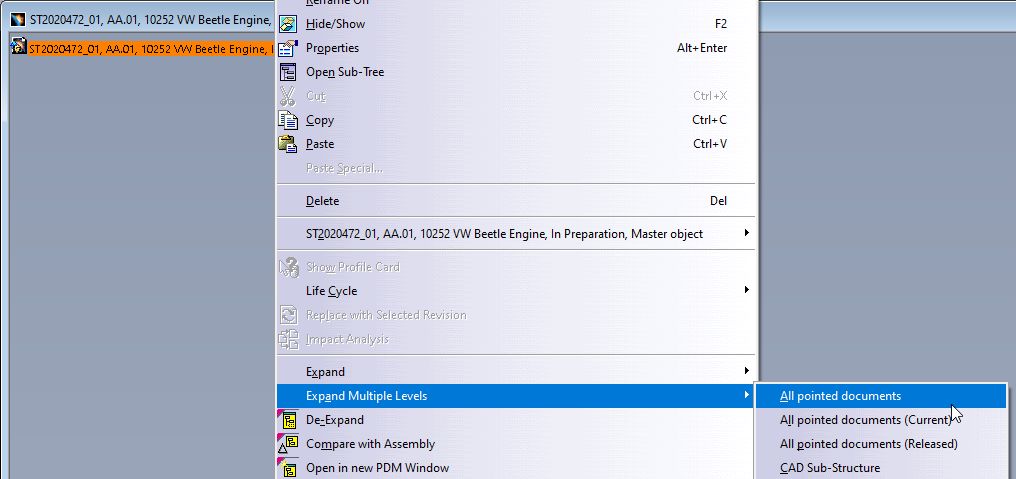
Then, instead of loading the complete structure with “Open” from the top assembly, it is possible to select any number of nodes (CATPart and/or CATProduct) in the tree and run the action “Open in Context” from the contextual menu (right click).
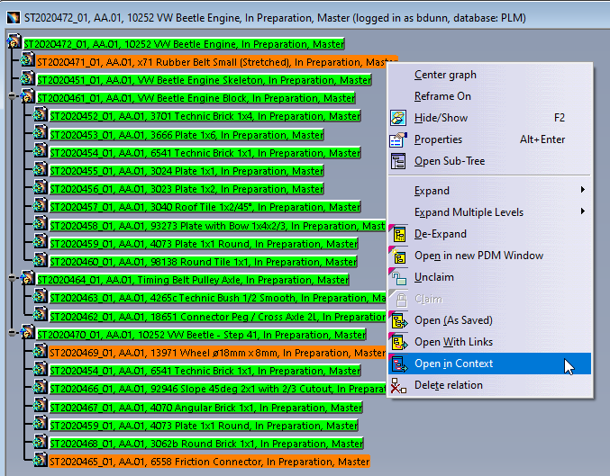
The complete PDM structure gets reduced to only the structure which contains the selected nodes and their parent node. This reduced structure is then opened to CATIA. The documents not selected for partial opening will be shown in the tree but their geometry will not be loaded*.

* However, if these ‘other’ documents have previously been opened in CATIA and their file is in your cache folder their geometry will also be loaded. They will be displayed as new documents, ‘not in PDM’. If the structure is saved these documents will be prompted to be saved as new references in the PLM. It is not recommended to save these. Instead, please close and reopen the structure normally if you need to make changes.
If you require to quickly review a 3D CATIA model it may be advantageous to use the 'preview in CATIA' command.
This will open documents much faster compared to the standard method of opening native files in CATIA, or even opening the converted STEP files into SpinFire Ult desktop viewer.
Whilst documents can be opened as equally quickly in the integrated PLM web viewer, this program has limited analysis capabilities. So depending on the requirements 'preview in CATIA' may be preferable. This option also allows you to quickly merge several models in a single scene in CATIA.
Note, opening a document as a preview should only be done if you require read access. If any changes are necessary, the document should be opened fully through the 'normal' methods.
Opening method:
Any 3D CATIA file can be previewed in CATIA by pressing the usual CATIA icon from the dashboard or profile card header and selecting the 'open as Preview in CATIA' button in the open options menu. If a CGR file is unavailable and waiting to be generated, it will be greyed out and a message will state that the CGR is not available yet. If a change has been made to the document and a new CGR file is being generated, a warning message will be displayed to warn you that the old CGR may be obsolete. Equally, this button is unavailable for drawings.
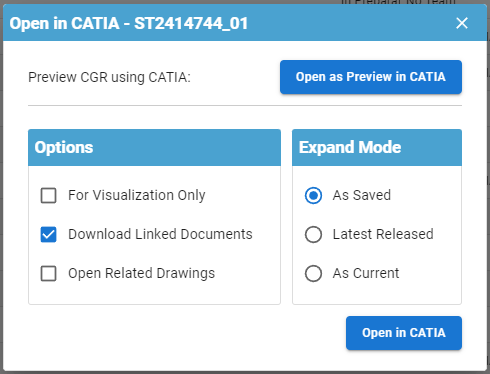

The file will be opened in a new window in CATIA. This will be displayed as 'Not in PDM' and you will be prompted to save them as new document numbers if you try to save. Please do not do this.

Please note, this method of opening differs from the 'for visualization only' option. The 'visualization only' simply renames the filename so it is not recognised by the connector, however it is still opening the native CATIA file type. This means it will be no quicker to load but you will be able to see all the modelling steps used to create the final model. Opening for preview uses a different filetype, CGR, which is much lighter and quicker to load, however you will only see the final model and you will not be able to interrogate the modelling steps.
Both methods can be used to open different versions of the same document number.
More:
Its important to know if your CAD structure contains 'non latest' versions of CAD Documents, especially if you need to work with the latest data, while the latest data might be available in SmarTeam only. Within the PLM and CATIA connector there are various ways you can check this.
- Through the use of dot icons in CATIA:
Orange, red and purple dot icons can be added to the standard CATIA symbols to indicate if a document is out of date. See this FAQ for more information on icons.
| Orange Dot: Not latest. At least one newer version exists only in SmarTeam (and not yet in the PLM). Note, the SmarTeam data sync process will occur each night, so the orange dot will appear the day after new SmarTeam data is created. | |
| Red Dot: Not latest. At least one newer version exists in the PLM, but all versions are available in the PLM. | |
| Purple Dot: The CAD document has out of date dependencies. |
- Through the 'Check dependencies' window in the PLM:
From a CAD documents profile card, it is possible to open up a tree structure of the CAD and check if any of the dependencies are ‘not current’. Click on the icon shown below in the profile card header.
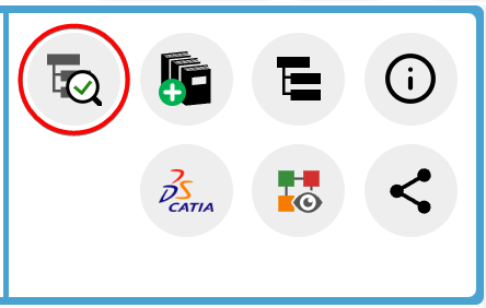
The new opened window will use the same colour code as used in CATIA and described above to highlight if a document is out of date or has out of date dependencies. There is a counter on the right-hand side to total how many documents are ‘non-current’, either due to new versions available in the PLM or SmarTeam.
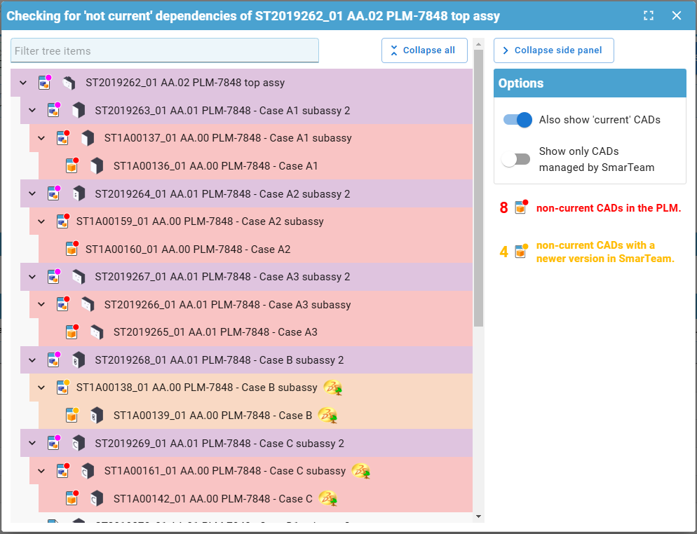
There are different filters available on the right, and a filter search field at the top. This box will filter for both document number and description.
- Through the PLM profile card header:
When viewing an individual CAD documents profile card, information will be displayed in the header if it is not the latest.
- If there is a new version available in the PLM (red dot), the following text will be displayed with a link to the latest version in the PLM:

- If it is the latest in the PLM but there is a new version available in SmarTeam (orange dot), the following text will be displayed:

- If its both not current in the PLM and SmarTeam (orange dot), there will be a link to the latest version available in the PLM, but it will also state there is an even newer version in SmarTeam:

- Through the CAD document attributes 'Is Current' & 'Is Current in SmarTeam'
When searching for CAD documents, or viewing them in a relationship grid from a profile card, you can see the 'Is Current' (in the PLM) & 'Is Current in SmarTeam' attributes

CATIA customised settings, such as shortcuts, can be saved in the PLM dashboard to be used when CATIA is reopened. This is also true for PWB setting changed in the options toolbar.
To save new customised settings, close the CATIA session in which the changes were made. Press the cog icon on the CATIA launcher to open the CATIA configurations window.
Enter a name for the new settings configuration. It will be saved and stored under one of the three main configurations that the CATIA session was originally opened under, and the settings were changed in.
Note the setting name may only contain alphanumeric characters and spaces, and be a maximum length of 64 characters. Configuration settings can also be deleted from this window by pressing the bin button next to them.
More: FAQ
Icons are used throughout the PLM and in the CATIA specification tree to quickly convey information. See the documentation below to find the explanation of each icon.
More: FAQ
A CAD document is made up of data, metadata. Some of this comes from CATIA such as the geometry, mass and material. Some of it comes from the PLM, Design code and RPG.
Two pieces of metadata can be changed in both the PLM and CATIA, the CAD definition and description. These two properties are mapped in both directions so can be modified in either platform and the data will be updated in the other. However, its important to understand when this information is transferred, so as not to loose any data.
- Data is pushed from the PLM to CATIA when a document is first opened.
- Data is pushed from CATIA to the PLM when a document is saved.
Why this is important?
If you have a document open in CATIA and change either the CAD definition or description in the PLM platform, these updates will not be pushed to the already open document in CATIA. The CATIA data will not be updated. Therefore, if the CAD document is subsequently saved in CATIA, the 'outdated' CATIA data will be pushed to the PLM overwriting the previous change.
Therefore, please do not change a documents metadata in the PLM if the document is already open in CATIA. Please do the changes in CATIA.
Note: If a document is modified in the PLM whilst it is open in CAD, when the CATIA tree is refreshed the definition will be updated because this displays data directly from the PLM connector. However, the CATIA data is not updated. This can be verified by viewing the data via right click > properties.
The first part of the FAQ linked below will show you a quick method of saving a CAD document without dependencies, like a CATPart. The second, more detailed section will describe how to save a structure where the files are linked to each other and will explore the different options available to you from the connector. The final part will explain you how to duplicate a CAD structure.
Please see the video below detailing the first scenario.
More: FAQ
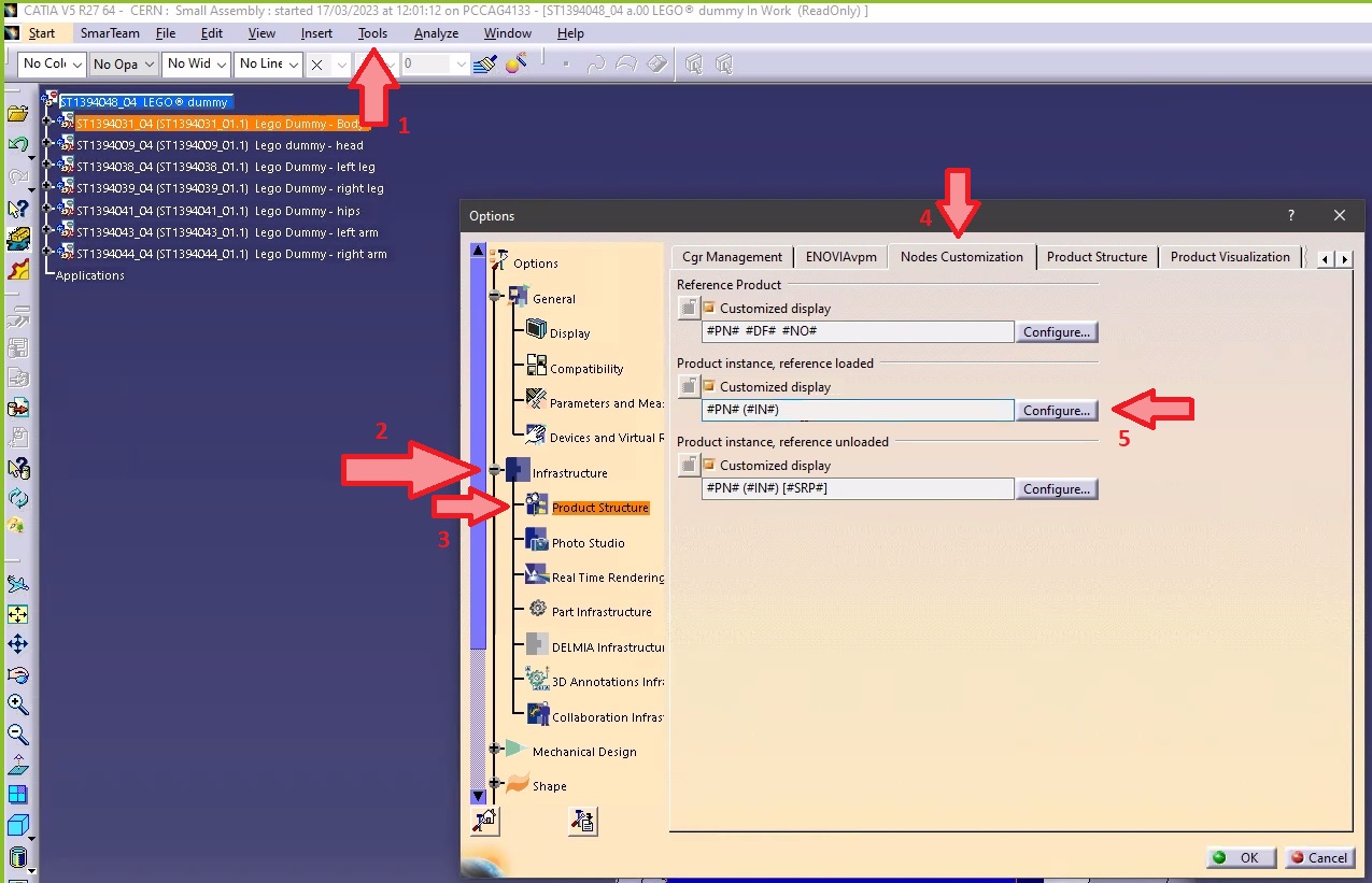
- Go to Tools ➞ Option ➞ Infrastructure ➞ Product Structure ➞ Nodes Customization.
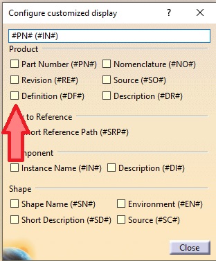
- Tick the "Customized display" (if not already ticked) and open the "Configure customized display" window using the "Configure...".
- In the new window add "Definition" ("#DF") to your product.
- Close. The CAD Definition should be changed in your CATIA tree.
Note 1: if in the same CATIA session, you visualize another product structure from the PLM, the Definition will appear twice.
Note 2: if you want to keep this setting by default for your future CATIA sessions, you need to save your settings.
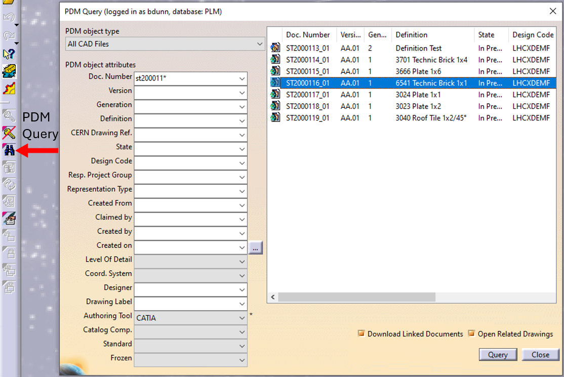
In CATIA, from the connector toolbar, clicking on the Query icon, you will be able to access the PDM Query dialog and to search for any CAD document previously uploaded to the PLM platform. Once the searched CAD Document has been found and selected, a double-click will open it in CATIA.
Note that the double-click corresponds to an Open as Current.
See the 'Opening' subgroup for related information
See more: Open CAD Document in CATIA
Any CATIA document saved in the PLM platform can be opened from there directly in CATIA. There are various methods, see below:
- From Profile card header

- From the PLM dashboard

- From the CAD Document Profile Card.

- From the profile card more menu
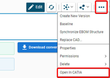
- From a search result grid, using the contextual menu.

See the 'Opening' subgroup for related information
See more: Open CAD Document in CATIA
For support, please send an email to plm-support@cern.ch.
A request will be automatically created in the Service-Now Platform. For urgent/blocking issues, please call the hotline: 160660
For CAD designers, it is also possible to report an issue from the PLM desktop application.
This way, the request created in Service Now will already contain some useful information for the PLM Support Team (PC name, date and time when the applications were launched, CATIA active document reference …).
This is the way to report the problems to be privileged.
Often enough, there is a need to switch between a 2D opened in CATIA to its corresponding 3D. In order to facilitate and quicken this task, it is possible to open the 3D directly from the 2D. To know more about this procedure, please check the document below.
In the following document there is an example that will show you step by step how to save it.
We consider Large Size Documents these ones that have a size of more than 106 bytes (~1Mb).
To avoid increase of the file size, you should follow these rules:
- Don’t use the catalog models blindly, keep all the details only if the design requires it.
- Avoid very detail representation of grids.
- Don't add unnecessary objects in Assemblies.
- Pay attention to the objects hidden or deactivated.
- Be aware with the scans.
- Don't use multibody to create Assemblies in CATParts.
To learn more how to work with large documents, please open the following document.
The document below will show you the procedure to export STL files using the dedicated workbench: STL Rapid Prototyping.
To use this function, you need to have a drawing opened in CATIA, then next step is to press Alt+P. It should open the dialogbox waiting for you to select a printer. In the "Size Selection" select the number that corresponds to the page size (for example to print in A4, choose number "4").
There is a combination to print it quicker: Alt+P+4 for a A4 size.
More: Quick Print
There is no function available in Catia V5 to do a 3D breakout view. But it is possible to realize such a view by following the methodology in the document below.
The multiple view mode is a new feature, it allows you to project the part or assembly on the whole of your screen for a presentation with views that you have chosen. You can save the display relative to an axis system or a face, without being in a sketch.
If you want to know something more about how to modify display or orientation, please follow the link below.
The graphic properties tool you can find in the top bar of the main CATIA workbenches.
To know more how to change them step by step, follow the document with instructions which is under.
When saving a CATIA file, a CGR file that represents said 3D is automatically created. However, some parameters can have an important influence on the size of the CGR, making the operation of opening the file in Preview or in Large Assembly more complex and demanding for the RAM.
For more information about the CGR file size, please explore the link below.
Please follow the instruction how to move it:
- Create a new Part.
- Add coordinate system.
- Find an existing part whose origin is centered in the assembly.
- Fix the components together.
- Create a coincidence constraint between the two axes systems.
To see step by step how to do it, please check the document below.
See also: How to move a Part while preserving the same coordinates system?
Sometimes there are some Parts that, because of migration or change of orientation/position, don’t have their coordinate system where desired.
In the document below, there are two options that you can follow to do it.
See also: How to move an assembly to another position while respecting the coordinates?
Parametric modeling aims to make “intelligent” models, which are directly driven by specifications, and which integrate the various knowledge around a project.
The link below will present the methodology and the basic tools and rules to follow in order to build parametric models or parts in the CATIA V5 environment.
It exists many types of links between CATIA documents. Among them, one is called contextual link, meaning that it exists a link between two parts in the context of a product. In some cases, this link can be replaced by a CCP link, that leads to the same result, without the drawback of the context.
For more details, please follow the document which is at the bottom.
By default, it is practicable to import Pro-E files into Catia V5 (.prt for parts, .asm for an assembly).
The document below shows how to allow the conversion of native PRO-E components into a modifiable and editable CV5 format. This method can also be used for other externals CAD format.
Please follow the steps below:
- Select the plane you want to orientate to activate the "Sketcher".
- Use the custom "Named Views" to capture this viewpoint.
- Exit the "Sketcher".
Now you are able to return anytime to the orientation you have just saved by selecting the saved position in the "Named Views".
To get the mass in a CATPart it’s important to put the material in the correct place in the document. The correct place to put the material is in the Part (and NOT in the PartBody). It’s important to follow this rule since the material in SmarTeam profile card will be taken from the part properties. If you put the material in the PartBody, SmarTeam will not show any material in the profile card.
In the link below you can find procedures step by step how to do it.
Thanks to a simple operation, you can hide all planes displayed in the assembly.
If you want to see a description of the methodology, the link below will show you how to do that.
In the document below you will find a detailed explanation of how to search for components in CATIA.
Below in the document there are a few steps to debugging CATIA models.
Be careful, make sure that the "Save" operation worked well before to close SmarTeam and Catia V5.
If "YES" have a look on following advise below: In case of doubt ➞ HotLine 16 06 60