CATIA - Assembly
Below is a group of How-to's that are related to the topic of 'Open/Import' in the CATIA - Assembly subcategory. Click on their links to find more information on these topics.
General:
- How to open a 3D from the corresponding 2D in CATIA?
- How to use the new TRACEPARTS Web V3?
- How to import applicative data
- How to Open a structure in context (partial loading)?
- How to open via neighbourhood search (Spatial search and opening)?
PLM Related:
Below is a group of How-to's that are related to the topic of 'Constraints & Positioning' in the CATIA - Assembly subcategory. Click on their links to find more information on these topics.
General:
Below is a group of How-to's that are related to the topic of 'Scenes & Views' in the CATIA - Assembly subcategory. Click on their links to find more information on these topics.
General:
Below is a group of How-to's that are related to the topic of 'Tools' in the CATIA - Assembly subcategory. Click on their links to find more information on these topics.
General:
Below are the remaining How-to's that are not present in other subgroups in the CATIA - Assembly subcategory. Click on their links to find more information on these topics.
General:
- How to avoid contextual links?
- How to hide all the planes in an assembly?
- How to avoid creating large size Assemblies?
- How to use the "Replace Component" command?
- Why the instance names do not have the same number as the instance name?
- How to create a variant without any impact on the original instance?
- How to create a group of CATParts?
- How to find and change a graphic property?
PLM Related:
- How to update a BOM in the PLM?
- How to project a BOM on a drawing?
- How to reorder a BOM?
- How to duplicate a structure?
You can duplicate an entire structure using the following tool from the PDM workbench contextual menu. It will duplicate the entire structure, top down from the selected node.

Once clicked, a list of the selected structure will open in the duplicate window, see the image below. As standard the whole structure will be set to duplicate, indicated with a green tick in the first column.
If this is not desired, documents can individually be set to ‘do not copy’ by selecting the row, then unticking the ’copy node’ check box and pressing ‘apply’ on the right side of the window. These nodes will then be highlighted with a red cross. Alternatively, the entire structure can be deselected by unticking the ‘duplicate all’ box at the top.
Note, documents that are not duplicated will still be copied into the new assembly.
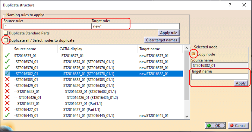
Target names must be defined for all duplicated items; however, these are only temporary as the new documents will automatically be assigned an ST document number on first save in the PLM. The names can be defined for all nodes by filling the “Source rule” and “Target rule” with a wildcard “*” as shown above. Alternatively, they can be defined individually using the box on the right.
Once finalised press okay and the duplicated structure will be opened in a new window. This can be saved into the PLM through a separate step, where new ST documents numbers will be assigned.
Associated drawings of the structure can be duplicated with the assembly. This setting can be enabled via the PWB Options window, found on the toolbar. If the duplication of drawings is enabled in this options window, they will be displayed in the list of objects to duplicate.


In the PWB it is possible to open a specific document in context, along with any documents that touch its bounding box in the specified context.
For example, if you have an engine and want to visualise only the parts that surround the crankshaft, this is quickly possible with this function. It prevents the requirement of having to open up the entire assembly, not only saving time but also improving the viewability (only see what is required).
To proceed, first select a CATPart in a PDM Structures window. Then in the contextual menu, click on Show Neighborhood.

A query window will show up in which you will have to specify the context assembly. The context is the assembly in which the selected CATPart belongs to (the CATPart does not have to be a direct dependency of the assembly, it can be part of a sub-assembly), and in which surrounding geometry will be search for. Double click on the queried context.

The result is a new PDM Structures Window, with the specified context assembly as the root object, that is filtered out with only the CAD Documents whose bounding boxes overlap with the bounding box of the original selected CATPart. You can open this reduced structure in CATIA. The rest of the structure that does not overlap with the main part, will be displayed in the CATIA tree, but no geometry will be loaded*.

Note: it is only possible to launch the neighbourhood query from a CATPart document, not from a CATProduct. However, it is possible to run several neighbourhood searches in a row. The content of each new PDM Structures Window can be opened and merged in the same CATIA geometry window. Also, the complete assembly can be opened in CATIA at any time.
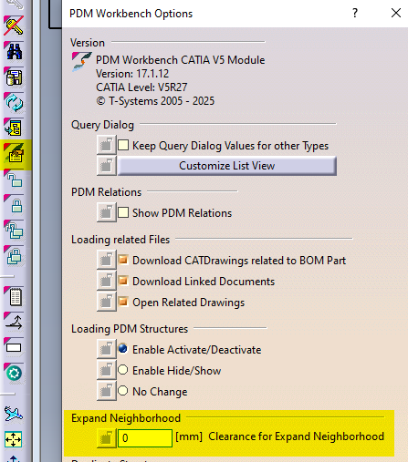
It is also possible to add a clearance around the bounding box of the selected CATPart, to find more CAD Documents. To modify the clearance value, please go to the connector options and enter the new value.
*If these ‘other’ documents have previously been opened in CATIA and their files are in your cache folder their geometry will also be loaded. They will be displayed as new documents, ‘not in PDM’. If the structure is saved these documents will be prompted to be saved as new references in the PLM. It is not recommended to save these. Instead, please close and reopen the structure normally if you need to make changes.
In the PWB it is possible to open on demand only certain selected nodes of the PDM structure in CATIA.
This may be useful when you only need to load a specific set of nodes from a heavy model, but would like to save it in context of the top assembly.
Firstly, open the assembly in the PDM structure window via the query tool, and expand the structure.

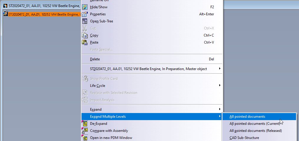
Then, instead of loading the complete structure with “Open” from the top assembly, it is possible to select any number of nodes (CATPart and/or CATProduct) in the tree and run the action “Open in Context” from the contextual menu (right click).
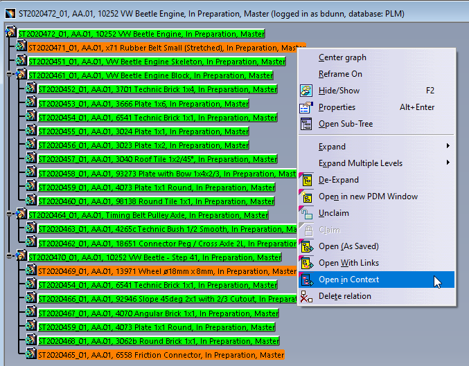
The complete PDM structure gets reduced to only the structure which contains the selected nodes and their parent node. This reduced structure is then opened to CATIA. The documents not selected for partial opening will be shown in the tree but their geometry will not be loaded*.

* However, if these ‘other’ documents have previously been opened in CATIA and their file is in your cache folder their geometry will also be loaded. They will be displayed as new documents, ‘not in PDM’. If the structure is saved these documents will be prompted to be saved as new references in the PLM. It is not recommended to save these. Instead, please close and reopen the structure normally if you need to make changes.
The order of the BOM is determined by the CATIA tree. The BOM is built based on the positions and quantities in the CATIA tree, using a top-down approach.
Please note:
- Only CAD Documents identified as 'Master' 'Representation type' are automatically included in the BOM. See the full FAQ to understand how to manually add documents of alternative 'representation types'.
- The first instance of a reference found in the tree structure is what determines its position in the BOM.
There are manual ways to override the CATIA positions & quantities, for further information on this see the FAQ below. However, you can also simply reorder the CATIA tree to order parts in the BOM as you desire. Use the 'Graph tree Reordering' function in CATIA to easily move the parts around.
The third button in the window can be used to move the part quickly next to any other, by selecting one in the list. Note when moving a part down from its current position, it will be placed under the document you select. When moving up, it will be placed above.
A BOM can be projected onto a drawing using the Title Block Editor (TBE).
When you click on the Title Block Editor icon in CATIA V5, it will open in a new window. The BOM can be found in the second tab, called “Bill of Materials”.
Check the “Bill of Materials” box to add the BOM to the title block of the drawing. Then click on “Generate & Save” to add the BOM and the title block to the drawing.
More: Title Block Editor FAQ
Further: BOM management in CATIA / PLM
The PLM uses an automatic engineering BOM (EBOM). This means every time you save an assembly the BOM will be created/updated on each 'claimed' or 'new' assembly node.
The BOM uses the positions and quantities of the instances in the CATIA tree, using a top-down approach.
Please note:
- Only CAD Documents identified as 'Master' 'Representation type' are automatically included in the BOM. See the full FAQ to understand how to manually add documents of alternative 'representation types'.
- The first instance of a reference found in the tree structure is what determines its position in the BOM.
- There are manual ways to override the CATIA positions & quantities, see the FAQ below.
You can also trigger a forced manual BOM synchronisation at any time from the “More” menu of the CAD Document profile card in the PLM platform.
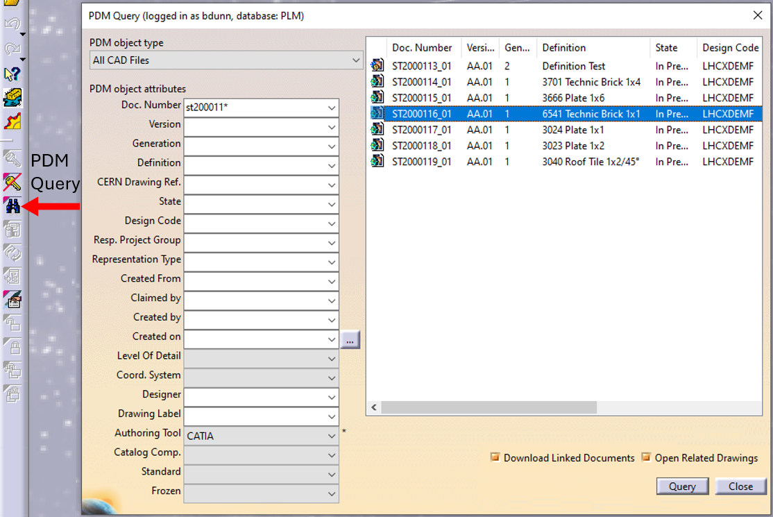
In CATIA, from the connector toolbar, clicking on the Query icon, you will be able to access the PDM Query dialog and to search for any CAD document previously uploaded to the PLM platform. Once the searched CAD Document has been found and selected, a double-click will open it in CATIA.
Note that the double-click corresponds to an Open as Current.
See the 'Opening' subgroup for related information
See more: Open CAD Document in CATIA
Any CATIA document saved in the PLM platform can be opened from there directly in CATIA. There are various methods, see below:
- From Profile card header

- From the PLM dashboard

- From the CAD Document Profile Card.

- From the profile card more menu
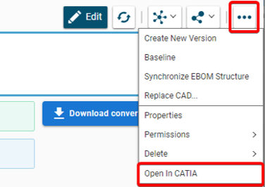
- From a search result grid, using the contextual menu.

See the 'Opening' subgroup for related information
See more: Open CAD Document in CATIA
Often enough, there is a need to switch between a 2D opened in CATIA to its corresponding 3D. In order to facilitate and quicken this task, it is possible to open the 3D directly from the 2D. To know more about this procedure, please check the document below.
To launch the TRACEPARTS Web from CATIA, click on the Icon:
This will open thee web page with list of companies' logos.
To find the component that you are looking for select the main filter or the starting letter of your desired category.
You can also skip it and scroll down until you find the company that you need.
When finally you find the page and select it, then click on the family you want and choose the references.
Under CAD models tab you can select CATIA V5 as your tool and then approve it.
This following document explains how to use the new Web TRACEPARTS (2021). Please check it to understand more how it works.
The scene tool in the “Assembly Design” workbench allows you to create multiple states of your model. By doing so, it enables you to study a variant of your assembly by defining specific component positions and specific attributes. The following document covers the main advantages and limitations of this tool.
A "Scene" is an alternative view of an assembly in a defined state. It enables you to study a variant of your Assembly by defining specific component positions and specific attributes. Please follow the document below to understand more details.
If you don't have an icon "Replace Component" in CATIA tools, find it this way:
- Click on the Part or Product in CATIA tree or "Edit" on the menu.
- Find the option named "Components".
- Choose:
- option "Replace Component in Session" which offers you as replacement the elements that are opened in the CATIA session,
- option "Replace Component" is the command which opens the search editor to find in SmarTeam the replacement.
The following document will show you more information about this function.
A positioning Matrix allows to place a component (Part, Component, Product) in space, relative to a higher component level, which will contain this matrix. If you want to understand more details, please click on the following document.
In the following document there is an example that will show you step by step how to save it.
- Edit the fix component constraint (double click on the constraint in the 3D or the tree).
- The following dialog box appears, then click on "More" and let the "Fix in space" checked.
- At that point you can change the values of translation and rotation (you can also change these values from the properties of the constraint).
- The component will take its new place.
- The components that were linked by constraints will update also.
If you want to know more, please check the document below.
We consider Large Size Documents these ones that have a size of more than 106 bytes (~1Mb).
To avoid increase of the file size, you should follow these rules:
- Don’t use the catalog models blindly, keep all the details only if the design requires it.
- Avoid very detail representation of grids.
- Don't add unnecessary objects in Assemblies.
- Pay attention to the objects hidden or deactivated.
- Be aware with the scans.
- Don't use multibody to create Assemblies in CATParts.
To learn more how to work with large documents, please open the following document.
- Start the DMU Navigator workbench.
- Select the document in the CATIA tree.
- In the "Insert" menu bar, select "Import Applicative Data".
- On the dialog box which appears, click the appropriate checkbox.
- Click "OK" to confirm.
In order to understand more how to do that, please consult the following document.
In an assembly, it is possible to duplicate a part or a product in order to create a variant without the original instance is impacted or even replaced with the new in the current session. There are few steps how to do it and you can find in the document below.
When we have to work with CGR files one of the biggest inconvenient that we can find is that is the difficulty to create constrains. Here (in the document below) we will show you a trick to be able to make some constrains of the CGR in one assembly (CATProduct).
This tool will make possible the calculation of the free volume of an assembly. It can be used, for instance, when designing a ventilation system.
In the document below, you can find an example which will show you step by step to get to the calculation of the free volume.
There is no function available in Catia V5 to do a 3D breakout view. But it is possible to realize such a view by following the methodology in the document below.
In an assembly, it is possible to create some groups of parts to ease their selection.
If you want to create a group:
- Go to the "DMU Navigator" workbench (Start ➞ Digital Mockup ➞ DMU Navigator).
- Click "Group".
- Select all the "objects" that need to be grouped, from the Catia three or directly in the 3D model.
- Click "Ok".
In the link under, you can see step by step how to do it.
If you want to use or to modify the group, you can easily find more detailed explanation in the document below.
The graphic properties tool you can find in the top bar of the main CATIA workbenches.
To know more how to change them step by step, follow the document with instructions which is under.
Please follow the instruction how to move it:
- Create a new Part.
- Add coordinate system.
- Find an existing part whose origin is centered in the assembly.
- Fix the components together.
- Create a coincidence constraint between the two axes systems.
To see step by step how to do it, please check the document below.
See also: How to move a Part while preserving the same coordinates system?
Sometimes there are some Parts that, because of migration or change of orientation/position, don’t have their coordinate system where desired.
In the document below, there are two options that you can follow to do it.
See also: How to move an assembly to another position while respecting the coordinates?
It exists many types of links between CATIA documents. Among them, one is called contextual link, meaning that it exists a link between two parts in the context of a product. In some cases, this link can be replaced by a CCP link, that leads to the same result, without the drawback of the context.
For more details, please follow the document which is at the bottom.
Q-Checker is a tool that checks the quality of a CATIA document. It will be automatically installed via CMF in all the PCs in the CATIA group.
If the tool is installed, in all the CATIA workbenches will appear this icon which is below.
![]()
It is possible to clear CATIA models from internal errors by:
- doing it one by one interactively,
- for several CO models simultaneously,
- for all models in a folder at once using a batch tool.
To follow step by step how to do it, please click on the link below.
Thanks to a simple operation, you can hide all planes displayed in the assembly.
If you want to see a description of the methodology, the link below will show you how to do that.
When Catia V5 files are manipulated, errors can appear, leading to troubles like ghost links. To solve this, the CATDUA (For Catia Data Upward Assistant) exist in the Catia V5 Desk This tool is powerful, but only treat documents one by one which can be painful for users, when dealing with assemblies. So, in order to facilitate the cleaning of models, CATDUAV5 Automation has been developed by support.
To learn more about this process, please refer to the document below.