
Tag: CATIA – CATPart
-
How to remove features (Holes, Logos, Chamfers, ect) from Parts using the Defeaturing tool?
How to remove features (Holes, Logos, Chamfers, ect) from Parts using the Defeaturing tool? Answer The Defeaturing tool in CATIA is used to simplify parts by removing recognized features such as holes, fillets, chamfers, and logos. It allows users to define filtering criteria to automatically select which features should be removed. A recent addition to
-
How-To Trim Intersecting Sketch Profiles Using Boolean Operations
How-To Trim Intersecting Sketch Profiles Using Boolean Operations Answer You can quickly remove parts of intersecting closed profiles by using Boolean trimming operations. Steps Commands and Results Notes
-
How To Create User Patterns with a Geometrical Set
How To Create User Patterns with a Geometrical Set Answer With CATIA R35, it is now possible to define the user pattern positions using a single geometrical set (or ordered geometrical set), enabling automatic updates when the set is modified. The User Pattern command allows you to duplicate a feature, a list of features, or a body at user-defined locations
-
How-to: Create a Chamfer Using Hold Curve (Angle & Length)
How-to: Create a Chamfer Using Hold Curve (Angle & Length) Answer Two new options have been added to the Chamfer command: These modes allow you to define the chamfers height based on a selected reference edge or curve (Hold Curve) instead of relying only on standard numeric definitions. This provides better control when the chamfer needs to align
-
How to use the “Keep Specifications” option with multiple features?
How to use the “Keep Specifications” option with multiple features? Answer In CATIA, the Keep Specifications option, previously available for single feature selection, is now also supported for multiple selected features in pattern and mirror commands. What does it do? This feature enables you to keep (use) the exact specifications of the original feature(s), on your patterns. To be more explicit, for example for holes drilled
-
How to use the Hole Analysis feature in CATIA R35?
How to use the Hole Analysis feature in CATIA R35? Answer The Hole Analysis feature allows you to identify and analyze all the holes present in a 3D part. You can use this tool to filter and review holes based on specific types, diameters, and depth ranges. Using the Hole Analysis Command 1. With your
-
How to create Multiholes in CATIA R35?
How to create Multiholes in CATIA R35? Answer The MultiHole command allows you to create multiple holes simultaneously in a part based on a sketch or a set of points, applying the same standard and preset definitions to all of them. Known Limitations Using the MultiHole Command 1. Click the MultiHole command.2. In the MultiHole
-
How to create Counterdrilled Holes with Countersunk Diameters in CATIA R35?
How to create Counterdrilled Holes with Countersunk Diameters in CATIA R35? Answer The enhanced Hole feature in CATIA R35 now allows you to create counterdrilled holes that directly include a countersunk diameter. Using the Countersunk Diameter Mode 1. Open the Hole Definition dialog box in your part. 2. Navigate to the Type tab. 3. In the Mode drop-down list, select Countersunk Diameter. 4. Specify
-
How to use the Pattern Analysis feature?
How to use the Pattern Analysis feature? Answer The Pattern Analysis feature allows you to identify and analyze all the patterns present within a CATPart. You can use this tool to filter and review patterns based on specific types and contexts. Using the Pattern Analysis Command 1. With your 3D Part open, select the Pattern Analysis command from the
-
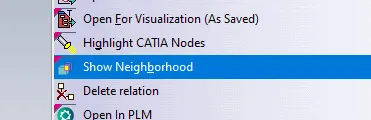
How to open via neighbourhood search (Spatial search and opening)
How to open via neighbourhood search (Spatial search and opening) In the PWB it is possible to open a specific document in context, along with any documents that touch its bounding box in the specified context. For example, if you have an engine and want to visualise only the parts that surround the crankshaft, this