CATIA
CATIA
Below is a list of acronyms that are used in relation to CATIA.
- BOM – Bill of Materials
- CGR – CATIA Graphical Representation
- GSD – Generative Shape Design
- PWB – PDM Workbench (PLM-CATIA connector)
- TBE – Titleblock Editor
- WB – Workbench
See the list of PLM Acronyms here.
See the list of SmarTeam Acronyms here.
To access CATIA via the PLM please press the CATIA icon in the top right of the dashboard screen.
Access to the CATIA connector is granted on request, therefore if you have not already done so please complete this form to work with CATIA. Prior to granting you access, we would ask for you to complete the relevant training, please see a link to the learning path to find the best suited course for you. Once you have been granted access you will have to download the required programs from CMF.
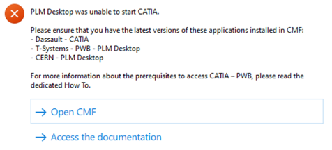
If you do not have the connector installed, or it is an out of date version, you will receive the following message when attempting to launch CATIA through the button on the PLM dashboard. This will remind you which applications must be installed and a link to CMF. There is also a link to documentation explaining the prerequisites required before running this application.
If CATIA is not installed the launch button will be greyed out.
If you're experiencing delays or failure when saving through the standard CATIA Connector, you can use the Emergency Save (also called Toolbox) function as a fallback to manually upload your work.
You can also use this tool to open existing CAD Documents for which you already experienced issues when opening or saving.
This guide walks you through the required steps, important limitations, and best practices to ensure your data is securely backed up.
Known Limitations
- No New Documents: The Toolbox will not handle new (never saved) CAD documents. These must be handled with the standard CATIA Connector before using this feature (see below).
- No BOM Computation will be launched after the save via the Toolbox. And running the e-BOM sync from the Profile Card of the assembly will not work.
So, at a point in time, it will be mandatory to save your structure with PWB, or to consider to update your BOM manually. - The CAD Documents open in CATIA using the toolbox will not display any PLM metadata in the CATIA tree, and appears as “Not in PDM”, thus cannot be saved using the usual CATIA Connector save. But they can be saved via the toolbox.
Using the Toolbox Save Command
If after a regular CATIA Connector save, you notice a failure, you can use the Toolbox Save Command.
The connector will save all the CAD Documents which are claimed in PLM AND modified in the CATIA Session before uploading them in the PLM.
- Let your CATIA session running. DON’T log off from the Catia Connector.
- Close the CATIA Connector Save window (if relevant).
- Access the tool, following this path in your file explorer:
\\cern.ch\dfs\Applications\PLMApps\CATIAPLMToolbox
and click on StartCATIAPLMToolbox_v1.exe
Note: for a regular usage, you can copy this shortcut on your desktop:
StartCATIAPLMToolbox.bat - Shortcut.lnk - The tool will start and will be associated to the PLM Desktop:
- Click the Save & Upload button.
- Read carefully the report and check the result in the PLM.
In case of doubt, call the CAD & PLM Support team.
Using the Open Command
- Open the CATIA session (or if CATIA is already running, use this session).
You do not have to log-in to the PWB CATIA Connector. However, if you want to work with PWB with other CAD Documents or if you will have to save brand new CAD Documents to the PLM, you must log-in. - Access the tool following this link:
\\cern.ch\dfs\Applications\PLMApps\CATIAPLMToolbox\StartCATIAPLMToolbox_v1.exe
Note: for a regular usage, you can copy this shortcut on your desktop:
\\cern.ch\dfs\Applications\PLMApps\CATIAPLMToolbox\StartCATIAPLMToolbox.bat - Shortcut.lnk - Click on Open and use the filters in the new pop-up window that appears to find the CAD document to open.
- Select it and in the “Open in CATIA” window, choose the expand strategy and the options you need, then validate.
- The tool will download the necessary files to your local machine then will open the selected CAD Document in CATIA.
Attention, CAD Documents open via the toolbox can only be saved with the toolbox. (And not via the usual CATIA Connector save)
Using the Open Profile Card Command
- Select one or several Documents or instances node in CATIA (the selection of features in a CATPart will be ignored)
- Click on the Open Profile Card button.
The Profile Card(s) corresponding to your selection will be displayed in the PLM Desktop.
Best Practices
- Use the Toolbox only as a last resort when standard saving is not responding, reports an blocking error or is taking too long or if you already experienced an issue when working with the same CAD Document.
- Always verify the saved structure afterward within the CATIA Connector interface.
Check for each of your recent modified and saved CAD Documents that the date & time of last modification of the native file is coherent with the save time.
- Notify the PLM Support Team if you consistently encounter performance issues or errors with the standard CATIA Connector.
- When you are aware that opening a given CAD Document returns an error, open directly via the Toolbox.
- In case you have inserted a new CAD Doc in your CATIA structure you are about to save with the toolbox:
Open this new CAD Doc in the new CATIA Window, save it using the CATIA Connector, and come back to the assembly window to save the assembly with the toolbox.
If you need further assistance, please reach out to our support team via the Contact Page or consult the detailed troubleshooting guide for CATIA connector issues.
You can duplicate an entire structure using the following tool from the PDM workbench contextual menu. It will duplicate the entire structure, top down from the selected node.

Once clicked, a list of the selected structure will open in the duplicate window, see the image below. As standard the whole structure will be set to duplicate, indicated with a green tick in the first column.
If this is not desired, documents can individually be set to ‘do not copy’ by selecting the row, then unticking the ’copy node’ check box and pressing ‘apply’ on the right side of the window. These nodes will then be highlighted with a red cross. Alternatively, the entire structure can be deselected by unticking the ‘duplicate all’ box at the top.
Note, documents that are not duplicated will still be copied into the new assembly.
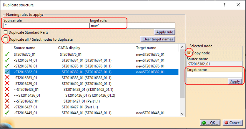
Target names must be defined for all duplicated items; however, these are only temporary as the new documents will automatically be assigned an ST document number on first save in the PLM. The names can be defined for all nodes by filling the “Source rule” and “Target rule” with a wildcard “*” as shown above. Alternatively, they can be defined individually using the box on the right.
Once finalised press okay and the duplicated structure will be opened in a new window. This can be saved into the PLM through a separate step, where new ST documents numbers will be assigned.
Associated drawings of the structure can be duplicated with the assembly. This setting can be enabled via the PWB Options window, found on the toolbar. If the duplication of drawings is enabled in this options window, they will be displayed in the list of objects to duplicate.


In the PWB it is possible to open a specific document in context, along with any documents that touch its bounding box in the specified context.
For example, if you have an engine and want to visualise only the parts that surround the crankshaft, this is quickly possible with this function. It prevents the requirement of having to open up the entire assembly, not only saving time but also improving the viewability (only see what is required).
To proceed, first select a CATPart in a PDM Structures window. Then in the contextual menu, click on Show Neighborhood.

A query window will show up in which you will have to specify the context assembly. The context is the assembly in which the selected CATPart belongs to (the CATPart does not have to be a direct dependency of the assembly, it can be part of a sub-assembly), and in which surrounding geometry will be search for. Double click on the queried context.

The result is a new PDM Structures Window, with the specified context assembly as the root object, that is filtered out with only the CAD Documents whose bounding boxes overlap with the bounding box of the original selected CATPart. You can open this reduced structure in CATIA. The rest of the structure that does not overlap with the main part, will be displayed in the CATIA tree, but no geometry will be loaded*.

Note: it is only possible to launch the neighbourhood query from a CATPart document, not from a CATProduct. However, it is possible to run several neighbourhood searches in a row. The content of each new PDM Structures Window can be opened and merged in the same CATIA geometry window. Also, the complete assembly can be opened in CATIA at any time.
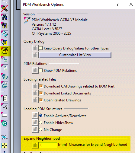
It is also possible to add a clearance around the bounding box of the selected CATPart, to find more CAD Documents. To modify the clearance value, please go to the connector options and enter the new value.
*If these ‘other’ documents have previously been opened in CATIA and their files are in your cache folder their geometry will also be loaded. They will be displayed as new documents, ‘not in PDM’. If the structure is saved these documents will be prompted to be saved as new references in the PLM. It is not recommended to save these. Instead, please close and reopen the structure normally if you need to make changes.
In the PWB it is possible to open on demand only certain selected nodes of the PDM structure in CATIA.
This may be useful when you only need to load a specific set of nodes from a heavy model, but would like to save it in context of the top assembly.
Firstly, open the assembly in the PDM structure window via the query tool, and expand the structure.

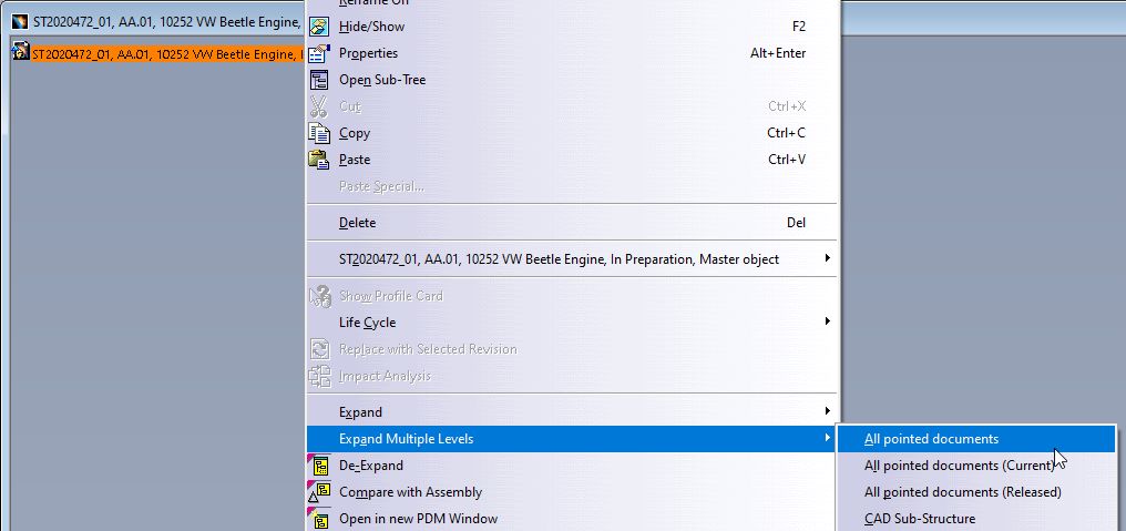
Then, instead of loading the complete structure with “Open” from the top assembly, it is possible to select any number of nodes (CATPart and/or CATProduct) in the tree and run the action “Open in Context” from the contextual menu (right click).
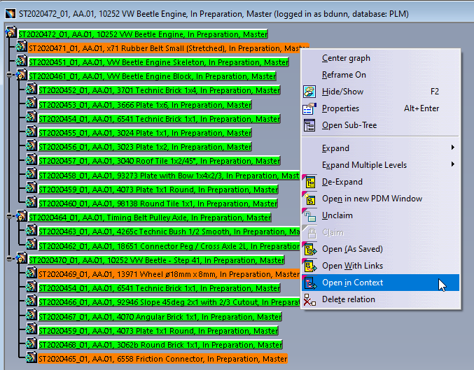
The complete PDM structure gets reduced to only the structure which contains the selected nodes and their parent node. This reduced structure is then opened to CATIA. The documents not selected for partial opening will be shown in the tree but their geometry will not be loaded*.

* However, if these ‘other’ documents have previously been opened in CATIA and their file is in your cache folder their geometry will also be loaded. They will be displayed as new documents, ‘not in PDM’. If the structure is saved these documents will be prompted to be saved as new references in the PLM. It is not recommended to save these. Instead, please close and reopen the structure normally if you need to make changes.
If you require to quickly review a 3D CATIA model it may be advantageous to use the 'preview in CATIA' command.
This will open documents much faster compared to the standard method of opening native files in CATIA, or even opening the converted STEP files into SpinFire Ult desktop viewer.
Whilst documents can be opened as equally quickly in the integrated PLM web viewer, this program has limited analysis capabilities. So depending on the requirements 'preview in CATIA' may be preferable. This option also allows you to quickly merge several models in a single scene in CATIA.
Note, opening a document as a preview should only be done if you require read access. If any changes are necessary, the document should be opened fully through the 'normal' methods.
Opening method:
Any 3D CATIA file can be previewed in CATIA by pressing the usual CATIA icon from the dashboard or profile card header and selecting the 'open as Preview in CATIA' button in the open options menu. If a CGR file is unavailable and waiting to be generated, it will be greyed out and a message will state that the CGR is not available yet. If a change has been made to the document and a new CGR file is being generated, a warning message will be displayed to warn you that the old CGR may be obsolete. Equally, this button is unavailable for drawings.
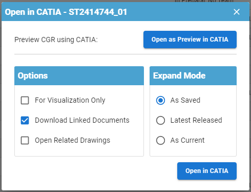

The file will be opened in a new window in CATIA. This will be displayed as 'Not in PDM' and you will be prompted to save them as new document numbers if you try to save. Please do not do this.

Please note, this method of opening differs from the 'for visualization only' option. The 'visualization only' simply renames the filename so it is not recognised by the connector, however it is still opening the native CATIA file type. This means it will be no quicker to load but you will be able to see all the modelling steps used to create the final model. Opening for preview uses a different filetype, CGR, which is much lighter and quicker to load, however you will only see the final model and you will not be able to interrogate the modelling steps.
Both methods can be used to open different versions of the same document number.
More:
Its important to know if your CAD structure contains 'non latest' versions of CAD Documents, especially if you need to work with the latest data, while the latest data might be available in SmarTeam only. Within the PLM and CATIA connector there are various ways you can check this.
- Through the use of dot icons in CATIA:
Orange, red and purple dot icons can be added to the standard CATIA symbols to indicate if a document is out of date. See this FAQ for more information on icons.
| Orange Dot: Not latest. At least one newer version exists only in SmarTeam (and not yet in the PLM). Note, the SmarTeam data sync process will occur each night, so the orange dot will appear the day after new SmarTeam data is created. | |
| Red Dot: Not latest. At least one newer version exists in the PLM, but all versions are available in the PLM. | |
| Purple Dot: The CAD document has out of date dependencies. |
- Through the 'Check dependencies' window in the PLM:
From a CAD documents profile card, it is possible to open up a tree structure of the CAD and check if any of the dependencies are ‘not current’. Click on the icon shown below in the profile card header.
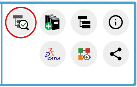
The new opened window will use the same colour code as used in CATIA and described above to highlight if a document is out of date or has out of date dependencies. There is a counter on the right-hand side to total how many documents are ‘non-current’, either due to new versions available in the PLM or SmarTeam.
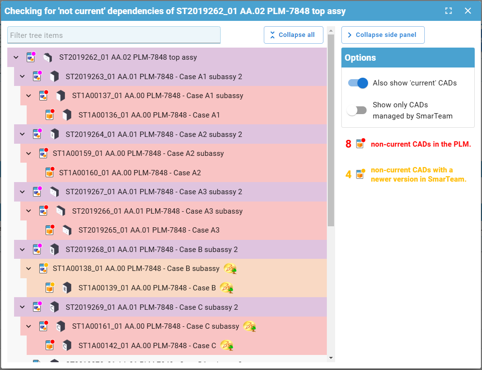
There are different filters available on the right, and a filter search field at the top. This box will filter for both document number and description.
- Through the PLM profile card header:
When viewing an individual CAD documents profile card, information will be displayed in the header if it is not the latest.
- If there is a new version available in the PLM (red dot), the following text will be displayed with a link to the latest version in the PLM:

- If it is the latest in the PLM but there is a new version available in SmarTeam (orange dot), the following text will be displayed:

- If its both not current in the PLM and SmarTeam (orange dot), there will be a link to the latest version available in the PLM, but it will also state there is an even newer version in SmarTeam:

- Through the CAD document attributes 'Is Current' & 'Is Current in SmarTeam'
When searching for CAD documents, or viewing them in a relationship grid from a profile card, you can see the 'Is Current' (in the PLM) & 'Is Current in SmarTeam' attributes

There are three main different CATIA configurations that can be selected from the drop down in the CATIA launcher menu, small, large and equipment systems. Below details the main differences in their set up:
- Small Assembly – Cache is deactivated so all parts are opened in design mode, resulting in them taking longer to load. The 3D Tessellation accuracy is higher than in the large setting. Assembly updates are automatic.
- Large Assembly – Uses cache so parts are opened in visualisation mode. To edit, or view at a greater accuracy, the parts must be manually activated into design mode. The 3D Tessellation accuracy is lower than in the large setting. Assembly updates are manual.
- Equipment systems – The settings are primarily the same as the large except the assembly updates are automatic. There is also a difference in the available workbenches. Equipment systems contains two extra workbenches; HVAC design and piping design. However, it also has one removed, raceway design (an electrical cabling discipline).
- Large assembly- Beta - Uses the same settings as large assembly with a few modifications to improve CATIA's stability when working with very large models. The Q-checker is not available in this configuration.
CATIA customised settings, such as shortcuts, can be saved in the PLM dashboard to be used when CATIA is reopened. This is also true for PWB setting changed in the options toolbar.
To save new customised settings, close the CATIA session in which the changes were made. Press the cog icon on the CATIA launcher to open the CATIA configurations window.
Enter a name for the new settings configuration. It will be saved and stored under one of the three main configurations that the CATIA session was originally opened under, and the settings were changed in.
Note the setting name may only contain alphanumeric characters and spaces, and be a maximum length of 64 characters. Configuration settings can also be deleted from this window by pressing the bin button next to them.
More: FAQ
Icons are used throughout the PLM and in the CATIA specification tree to quickly convey information. See the documentation below to find the explanation of each icon.
More: FAQ
A CAD document is made up of data, metadata. Some of this comes from CATIA such as the geometry, mass and material. Some of it comes from the PLM, Design code and RPG.
Two pieces of metadata can be changed in both the PLM and CATIA, the CAD definition and description. These two properties are mapped in both directions so can be modified in either platform and the data will be updated in the other. However, its important to understand when this information is transferred, so as not to loose any data.
- Data is pushed from the PLM to CATIA when a document is first opened.
- Data is pushed from CATIA to the PLM when a document is saved.
Why this is important?
If you have a document open in CATIA and change either the CAD definition or description in the PLM platform, these updates will not be pushed to the already open document in CATIA. The CATIA data will not be updated. Therefore, if the CAD document is subsequently saved in CATIA, the 'outdated' CATIA data will be pushed to the PLM overwriting the previous change.
Therefore, please do not change a documents metadata in the PLM if the document is already open in CATIA. Please do the changes in CATIA.
Note: If a document is modified in the PLM whilst it is open in CAD, when the CATIA tree is refreshed the definition will be updated because this displays data directly from the PLM connector. However, the CATIA data is not updated. This can be verified by viewing the data via right click > properties.
The order of the BOM is determined by the CATIA tree. The BOM is built based on the positions and quantities in the CATIA tree, using a top-down approach.
Please note:
- Only CAD Documents identified as 'Master' 'Representation type' are automatically included in the BOM. See the full FAQ to understand how to manually add documents of alternative 'representation types'.
- The first instance of a reference found in the tree structure is what determines its position in the BOM.
There are manual ways to override the CATIA positions & quantities, for further information on this see the FAQ below. However, you can also simply reorder the CATIA tree to order parts in the BOM as you desire. Use the 'Graph tree Reordering' function in CATIA to easily move the parts around.
The third button in the window can be used to move the part quickly next to any other, by selecting one in the list. Note when moving a part down from its current position, it will be placed under the document you select. When moving up, it will be placed above.
A BOM can be projected onto a drawing using the Title Block Editor (TBE).
When you click on the Title Block Editor icon in CATIA V5, it will open in a new window. The BOM can be found in the second tab, called “Bill of Materials”.
Check the “Bill of Materials” box to add the BOM to the title block of the drawing. Then click on “Generate & Save” to add the BOM and the title block to the drawing.
More: Title Block Editor FAQ
Further: BOM management in CATIA / PLM
The first part of the FAQ linked below will show you a quick method of saving a CAD document without dependencies, like a CATPart. The second, more detailed section will describe how to save a structure where the files are linked to each other and will explore the different options available to you from the connector. The final part will explain you how to duplicate a CAD structure.
Please see the video below detailing the first scenario.
More: FAQ
The PLM uses an automatic engineering BOM (EBOM). This means every time you save an assembly the BOM will be created/updated on each 'claimed' or 'new' assembly node.
The BOM uses the positions and quantities of the instances in the CATIA tree, using a top-down approach.
Please note:
- Only CAD Documents identified as 'Master' 'Representation type' are automatically included in the BOM. See the full FAQ to understand how to manually add documents of alternative 'representation types'.
- The first instance of a reference found in the tree structure is what determines its position in the BOM.
- There are manual ways to override the CATIA positions & quantities, see the FAQ below.
You can also trigger a forced manual BOM synchronisation at any time from the “More” menu of the CAD Document profile card in the PLM platform.
Please follow the necessary training before using the PLM. You can access the training and learning path here, this will help you identify what training is necessary for you depending on your previous experience and knowledge.
Training on the CATIA-PLM connector (PWB) is a prerequisite to being granted access to CATIA via the PLM. Once you have completed the training please complete this form to request access to the PLM and CATIA connector.
Prior to having the access rights, you will receive an error message when attempting to launch CATIA, and you will not be able to view the connector package in CMF. Please complete the form above.
If you would like a refresher after completing the training please see the document at the bottom of this page, it explains the basic concepts to help you get started. Also see the video below which walks you through the basics steps of using the CATIA connector, such as opening and saving a document.
For more information on some of the steps covered in this video, please see these dedicated how-to's.
- How to access CATIA via the PLM?
- What's the difference between the different CATIA configurations?
- How to search using the PLM dashboard?
- How to open a CAD document from the PLM?
- How to open a CAD document from CATIA using the connector?
- How to save a new CAD document in the PLM from CATIA?
- How to book a specific CERN Drawing Reference before the creation of the Drawing?
- How to set an existing CERN Drawing Reference (CDR) to a new Drawing?
More: FAQ
The CGR and Approximate format contains only the graphical representation of the geometry. These options allows you to choose different appearances of the linework of your Drawing.
The CGR files are facetted models for visualisation that can't be edited but they can be used for interference checks. It can also be used as a light representation of a native model that is too heavy for the computer to load, so it is helpful with big assemblies.
The Approximate mode reduces memory consumption and it consumes even less memory and is faster than CGR.
To edit this properties go to the Drawing and right-click on the frame, then select "Properties". Scroll down in the new window and look for the section "Generation Mode". Below you can find the "View generation mode" and from there you can choose CGR or Approximate view.
![]() How to create a dimension relying on a 3D point, projected in a view in approximate mode?
How to create a dimension relying on a 3D point, projected in a view in approximate mode?
To edit this properties go to the Drawing and right-click on the frame, then select "Properties". Scroll down in the new window and look for the section "Generation Mode". Below you can find the "View generation mode" and from there you can choose CGR or Approximate view.
To know more about CGR or Approximate mode, please check the link below.
![]() How to create a dimension relying on a 3D point, projected in a view in approximate mode?
How to create a dimension relying on a 3D point, projected in a view in approximate mode?
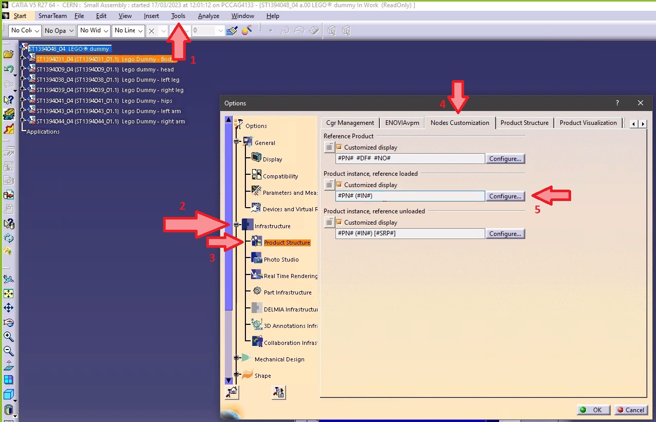
- Go to Tools ➞ Option ➞ Infrastructure ➞ Product Structure ➞ Nodes Customization.
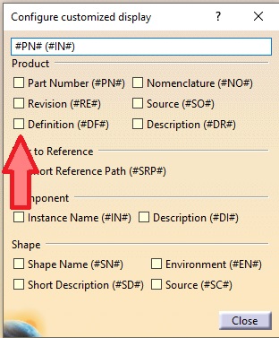
- Tick the "Customized display" (if not already ticked) and open the "Configure customized display" window using the "Configure...".
- In the new window add "Definition" ("#DF") to your product.
- Close. The CAD Definition should be changed in your CATIA tree.
Note 1: if in the same CATIA session, you visualize another product structure from the PLM, the Definition will appear twice.
Note 2: if you want to keep this setting by default for your future CATIA sessions, you need to save your settings.
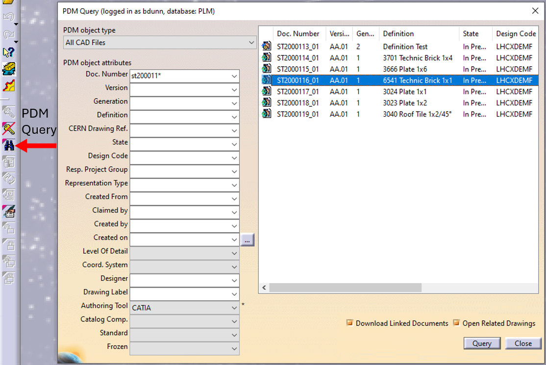
In CATIA, from the connector toolbar, clicking on the Query icon, you will be able to access the PDM Query dialog and to search for any CAD document previously uploaded to the PLM platform. Once the searched CAD Document has been found and selected, a double-click will open it in CATIA.
Note that the double-click corresponds to an Open as Current.
See the 'Opening' subgroup for related information
See more: Open CAD Document in CATIA
Any CATIA document saved in the PLM platform can be opened from there directly in CATIA. There are various methods, see below:
- From Profile card header

- From the PLM dashboard

- From the CAD Document Profile Card.

- From the profile card more menu
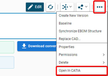
- From a search result grid, using the contextual menu.

See the 'Opening' subgroup for related information
See more: Open CAD Document in CATIA
For support, please send an email to plm-support@cern.ch.
A request will be automatically created in the Service-Now Platform. For urgent/blocking issues, please call the hotline: 160660
For CAD designers, it is also possible to report an issue from the PLM desktop application.
This way, the request created in Service Now will already contain some useful information for the PLM Support Team (PC name, date and time when the applications were launched, CATIA active document reference …).
This is the way to report the problems to be privileged.
Access to the CATIA connector is granted on request, therefore if you have not already done so please complete this form to work with CATIA. Prior to granting you access, we would ask for you to complete the relevant training, please see a link to the learning path to find the best suited course for you.
Once your computer is added in the NSC (to complete this process, the admin or the main user of the computer must accept a request sent via email), you will be able to install the CATIA connector via the CERN CMF installation manager, through the icon as shown in the image below.
Note that only Windows 10 physical machines managed by CMF are eligible for CATIA V5 installation.

The main purpose of the toolbox is to design a multi-layer's coil or magnet spacers defined by points coordinates stored in a text file. You can also use this tool to estimate the quality and conformity of generated parts by searching intersection between correspondent coils and spacers. Tool can be used to check the quality of generated spacers by finding distance between the points from text file and the used ones for the design. Tool can be used for exporting constructed data in STEP format.
If you have more questions about this, please check the document under.
To import you need the "Part Template" tool. This can create some 3D points in Catia V5 from their coordinates stored in one Excel file. The created points can be automatically renamed if the name information is available in the Excel file. An optional feature allows building straight lines between every point.
If you want to know details, please check the document below.
The tool that you have to use is a "Power Copy". To use it, a Part must be activated. If you want to know more details, please open the document which is under.
This tool generates a CATPart from a CATProduct, using the "Generate CATPart from Product..." command. Then the tool scans the original Product to search for the materials associated to the parts. It is also possible to run this macro from an existing CATPart generated previously, if the corresponding Product is also opened in Catia V5 to add the material and definition parameters.
If you want to know more about this tool and how to generate this process, please follow the document below.
The "Optimization" workbench is available in Catia V5. It is possible to use it to solve more or less complex problems. You will find in the document below some simple examples in which some optimizations are used and some information on how to put them in place.
The CATIA Knowledgeware regroup a lot of functions: rules, optimizations, templates... that allow you to create generative tools or parametric constructions. Most of the common functionalities we can use in CATIA are contained in "Product Synthesis" solutions.
To start, go to the "Mechanical Design" and then to the "Generative Sheetmetal Design" workbench. Click on the icon and specify the correct parameters of the sheet that you are going to work with: "Thickness", "Default Bend Radius" and "Bend Extremities". The "Sheet Metal Parameters" feature should be added in the specification tree.
If you want to see step by step how to do it, please follow the document below.
The following document has an explanation how to do this step by step. Please check it if you want to know more.
The "Surface Curvature Analysis" is used to find the curvature of the surface or the face of a solid. You can perform analysis in "Part Design" as well as in "Generative Shape Design". If you want to see how the procedure should look like, please open the document below.
Split is an operation where one element is cut by another element.
Trim is an operation in which two elements cut each other mutually.
If you want to see more details and differences between these two functions, please check the document below.
To get the surface from land contour lines you need to proceed from the isolation of the relevant geometry, then the improvement of the quality of the geometry and then the generation and extraction of 3D points. Then you should transform the 3D points into the cloud of points, generate a mesh and then finally auto create a surface feature. If you want to know more details about it, please follow the link below with explanation.
Distance analysis tool could be used to measure distance between surfaces which are very close to each other. The distance is computed in several points so as result we will get the distance distribution between chosen surfaces. You can find "Distance Analysis" tool in "Shape Analysis" toolbar which is available in “FreeStyle” workbench. To find it, follow the instructions on the document below.
You can now create planes between two existing planes at once.
Follow the instruction to do this:
- Click on the "Replication" toolbar.
- Find the icon "Planes Between".
- When the dialog box appears, select two planes between which the new planes must be created (it cannot be parallel).
- Indicate the number of planes.
- Click "Preview" to see the plane created.
- Click "OK".
- Planes are added to the tree specifications.
For more details, please check the document below.
For objects with features that are symmetrical in the thickness direction, a middle surface can be created using functions from the Generative Shape Design (GSD) workbench. There are several options on how this can be done.
In the following document you can find three scenarios that a user can basically come across:
- All of the object’s relevant features are symmetrical in the thickness direction.
- Some of the object’s relevant features are asymmetrical in the thickness direction.
- It is possible to create the solid from the surface rather than the other way around.
To know it better, please check the methodology in the link.
A 3D curve can be created in space or lie on a geometrical element, or both. When the curve lies on a geometrical element, associativity can be kept. It is also possible to edit, delete or add points when creating the curve, or after. A 3D curve is a very fast and flexible tool which is really different from a "Spline".
- route electrical wires,
- work with Bezier Nurbs,
- create a guide curve for a sweep or a rib.
From the following document, you will learn new possibilities about 3D curve from "FreeStyle" workbench.
The 3D curve function is available in the Freestyle workbench. With the 3D curve function, it is possible to create associative curves in which you can add or remove points during the creation of the curve and also later.
If you want to know more details, when to use it or how to modify it, please check the document below.
See also: How to create an advanced 3D curve?
If you want to learn how to create a run and place a "Pipping Part", please study the document below which inside you can find an example how to design it.
Often enough, there is a need to switch between a 2D opened in CATIA to its corresponding 3D. In order to facilitate and quicken this task, it is possible to open the 3D directly from the 2D. To know more about this procedure, please check the document below.
The document below is only applicable to the Integration team.
For the other users, if an A0 sheet is too small, please follow this link: CLICK.
Due to a limitation in CATIA V5 it is impossible for users to place multiple orthogonal leaders for geometrical tolerances.
The workaround consists in:
- Hold down Shift key before selecting the first reference of the geometrical tolerance, this will create the first leader.
- Right click on the tolerance and select "add new leader" and select other reference (without holding Shift).
- Right-click on the extremity of the arrow (yellow mark) and select "Add a Breakpoint", this will add yellow mark on the leader where the breakpoint is located.
- Hold down the Shift key and try to move the newly created Breakpoint (new yellow mark).
- The breakpoint will jump to the main geometrical element leader and it looks like a new perpendicular leader.
- You can right-click on the Breakpoint again and select "Rigid", this will help to keep it in place.
Each time you want to adjust the perpendicularity of the leader created via the breakpoint, move it with pressed down Shift key and the point will adjust perpendicular to the main geometrical element leader.
A drawing can be called “too large” when the native file size is a number with more than 6 digits. Unfortunately, there is not a perfect solution but in the document below there are different methods and options that depending on each case can be used to generate a lighter drawing. Please follow the link to understand it better.
In some cases, you can use in the "Tools Palette" and it can be recognized during the creation of the dimensions. It is always possible to add these points manually and after using them, create the dimensions. The blue lines and the intersection points are not visible when the document is outside CATIA (printed or in CDD).
If you want to understand more details and how to represent the prolongation lines to the intersection point, please open the following document.
- Select one or more holes in the drawing.
- Click "Hole Dimension Table" in the dimensioning toolbar.
- The Axis System and Table Parameters should be displayed.
To know more about the dialog box and what to type or select, please check the following document.
In CATIA it is not possible to add the symbol envelope direct to a diameter.
Here there is a workaround to add it if the dimension:
- is not a diameter or a radius
Properties ➞ Dimension Texts ➞ Main Value ➞ click on the symbol - is a diameter or a radius
Properties ➞ Dimension Texts ➞ Prefix Suffix ➞ choose the group of symbols (first icon) ➞ Main Value ➞ click on the symbol
If you want to see step by step how to do it, please follow the instruction which is in the document below.
The drawing standard is stored in the drawing upon the creation, this standard 'copy' is kept independently this means it will not automatically update when the standard settings of CATIA change.
There is a procedure step by step how to do it:
- Open and Check-out the Drawing.
- Go to the File ➞ Page Setup.
- In Page Setup window select the standard of the drawing like ISO_CERN.
- Push the "Update" button.
- Update the elements which changed in the standard.
If you want to know more details about this procedure, please check the document which is under.
Pagination
- Previous page
- Current page 1
- Page 2
- Page 3
- Next page